5

I have a question regarding potentiometer example:

https://www.arduino.cc/en/Tutorial/AnalogReadSerial

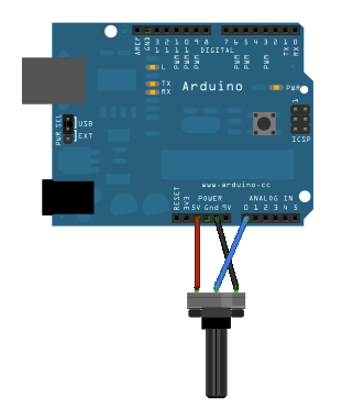
enter image description here

If I turn the potentiometer to the marginal position and have 5V at A0 (and almost zero resistance at the pot), what limits the current flowing through the circuit?

2 Answers 2

5

A0 input is high impedance, so very little current is flowing into A0. The value is so small that you can simplify that it flows only from +5V through the potentiometer to GND.

For some applications, when you are measuring high-impedance sources (a source that can deliver very little current) this simplification may not be correct.

You can find more detailed explaination in Atmel application note:

http://www.atmel.com/images/atmel-8456-8-and-32-bit-avr-microcontrollers-avr127-understanding-adc-parameters_application-note.pdf

4
  • Sorry for maybe a stupid question, but if the current flows through the pot with close to zero resistance from +5V to GND, isn't I short-circuting an Adruino that way? Commented Jan 31, 2016 at 11:09
  • Resistance between +5V to GND is rather high and equal to nominal potentiometer resistance. It depends what pot you've choosen. Check it with a meter or check for value printent on the case. If it haven't smoked yet, it must be high enough. :-) Potentiometer works as a voltage divider with current flowing mainly through Z1 and Z2: en.wikipedia.org/wiki/Voltage_divider Commented Jan 31, 2016 at 11:18
  • 3
    Oh, got it finally! Resistance between +5V and ground is always 10 kOms, but resistance between +5V and OUT can vary from 0 Ohms to 10 kOhms. Commented Jan 31, 2016 at 11:45
  • Exactly. Now, the important thing is that the source impedance will vary. If you swipe the potentiometer to +5V, source impedance will be close to 0 (low Z1, high Z2). If you turn it to let's say, 0.1V, the source impedance will be close to 10k (high Z1, low Z2). This will start being an issue if you use high-resistance potentiometers (100s kiloohms), as the source will become to weak for the ADC, resulting in errors. We use buffers and signal conditioning circuits to mitigate those issues. Commented Jan 31, 2016 at 12:05
3

Assuming A0 is set to input then it is a high-impedance input. That is, the input has a high resistance, and only consumes enough current to "sample" the voltage.

2
  • Please, take no offence for giving an accepted answer to IOB Toolkit Team. I suppose it's in the best interest for community to distribute the rep-wealth evenly among its members. Commented Jan 31, 2016 at 10:36
  • I'm not offended. They typed their answer while I was typing mine. By the time I pressed "Submit" their answer was there. I agree about distributing rep, BTW. :)
    – Nick Gammon
    Commented Jan 31, 2016 at 20:21

Your Answer

By clicking “Post Your Answer”, you agree to our terms of service and acknowledge you have read our privacy policy.

Not the answer you're looking for? Browse other questions tagged or ask your own question.