4

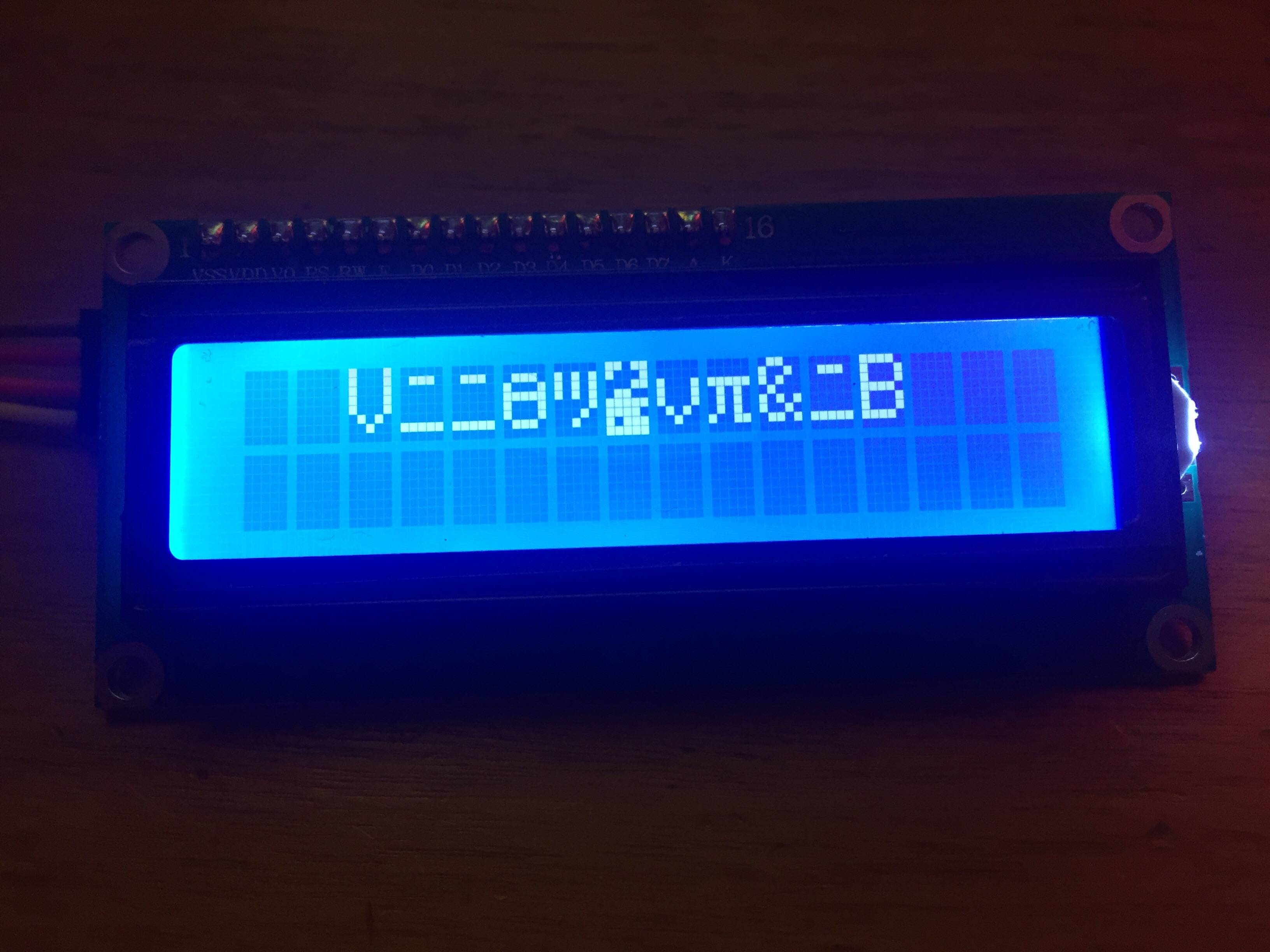
I have connected an LCD with an I2C backpack to my Arduino Uno but it prints the wrong characters. The weird thing is that it worked fine for a while and when I updated the code (but didn't change anything to do with the LCD) it started displaying the wrong characters. This happened earlier today too. That time, reinstalling the LiquidCrystal library worked, but it doesn't now.

Does anyone know what might be the problem so I can fix it permanently?

The LCD's SDA and SCL are connected to A4 and A5 respectively and I'm running this code:

#include <Wire.h> 
#include <LiquidCrystal_I2C.h>

LiquidCrystal_I2C lcd(0x27,20,4);  // set the LCD address to 0x27 for a 16     chars and 2 line display

void setup()
{
  lcd.init();
  lcd.backlight();
  lcd.setCursor(0,0);
  lcd.print("Hello, world!");
}


void loop()
{
    }

and this is what's displayed on the screen:

some random characters

2
  • add a picture of your wiring please!
    – tuskiomi
    Commented Jan 1, 2016 at 21:14
  • Is "LiquidCrystal_I2C lcd(0x27,20,4);" that right for this display? It looks like a 16X2 display. Please post a picture of the LCD adapter. Commented Jan 1, 2016 at 21:47

3 Answers 3

7

If you look up the ASCII codes for what you sent vs what was displayed, and also look at "Table 4 Correspondence between Character Codes and Character Patterns (ROM Code: A00)" in an HD44780U spec sheet, you will find hexadecimal values like the following.

  • e 65, V 56
  • l 6C, ニ C6
  • o 6F, θ F2
  • o 6F, π F7
  • r 72, & 26
  • d 64, B 24
  • and so forth.

It appears that the high nibble of what you sent is being used as the low nibble of what is displayed, and the low nibble is being used as the high, but with some bits sometimes going wrong. Note, a space is 0x20, and the reverse of that is 0x02, which would access a character from the character-generator RAM, which will contain random bits and produce a random blob as in your picture.

If your mis-specification of display size (20, 4 vs 16, 2) isn't responsible for the problem, then maybe there is a hardware problem with the backpack you've soldered on to the LCD. Look at it under a bright light, using a binocular parts-examination microscope if you've got one, and see if there are loose solder particles, extra solder flux, or loose solder connections on that board. If you have an oscilloscope, check if your I2C signals are clean and have full swing.

3
  • 1
    I doubt the swapping of nibbles is due to a poor soldering. But +1 for wading through the datasheet to find the link. Commented Jan 2, 2016 at 0:40
  • 1
    Thank you very much @jwpat7 and @brianrho! Strangely, when I reconnected my lcd with this code just now, it randomly worked again. Anyway, I fixed the 20,4 to 16,2 just to be sure and if it starts acting up again I'll have a close look at the backpack. Commented Jan 2, 2016 at 12:52
  • Thanks, @WoutervanDijke, I had the same issue, just my problem was that I was printing in the loop() without setting cursor to 0,0 position, hence internal LCD memory got corrupted and it started to print random characters. I fixed the code, but it won't help, just after re-connecting 5V power pin,- LCD started to behave as normal. Hence power pin re-connect works as "factory reset" button for LCD. Cool ! You saved my life :-) Commented Dec 11, 2022 at 15:10
2

From what I can see, it seems, in this line:

    LiquidCrystal_I2C lcd(0x27,20,4);

wrong parameters have been passed to the constructor. The last two arguments are supposed to indicate the number of columns and rows on the screen. Your screen has 16 columns and 2 rows, whereas you passed 20 columns and 4 rows to the constructor. This could be the problem.

2

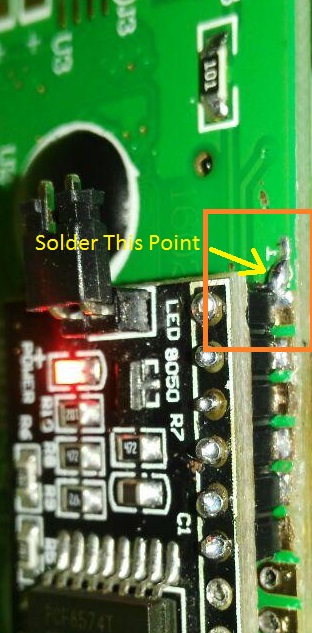
I experienced this while using a STM32f429 discovery board, and I found out there are two reasons that this happens.

  1. when using a fast microcontroller (180 MHz clock), if you send I2C packet consecutive LCD may not be that fast to understand it and as James said in other post LCD may lose some packet and get confused. To cope with that you have to put a delay between your packet.
  2. If you reset your MCU board while your LCD is writing something without cutting off power, LCD may get first nibble but lose the second 4bit nibble and interprets your initialize data as second nibble data to show on LCD and simply get confused. If LCD had something like software reset it could help but I did not find anything in datasheet. Though I think there is a hardware walkaround

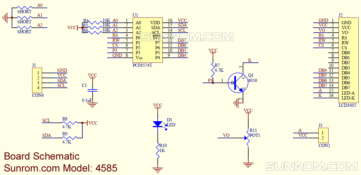
 LCD I2C module based PCF8574 Schematic

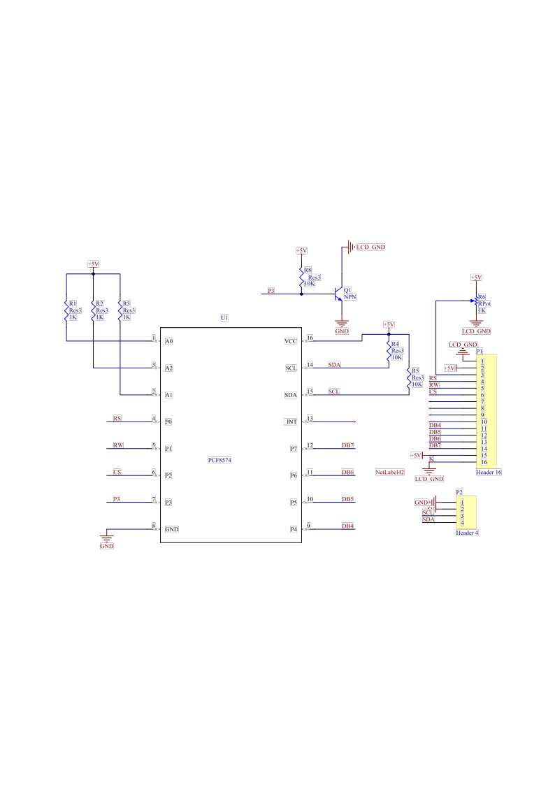
if you could disconnect K in 8050 transistor and connect LCD Ground to that point then you could disconnect and connect LCD power just by toggle P3 pin through PCF8574 IC when you are initializing your LCD.actually you will lose some control over LCD backlight. you can consider R/W pin too because almost all firmware just write on LCD and simply lower this pin. I bring the purpose schematic in below

modified schematic

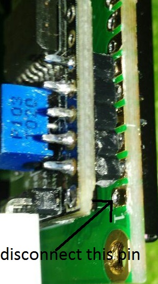
in Module simply disconnect ground pin from module and LCD and in LCD board connect K pin to ground as i put the image here

disconnect Ground PIN

connect Baklight Kathode to Ground PIN

in your Code When you are Initializing write 0xF7 in I2C and Delay for 200 ms then write 0 for and delay 100 ms then do your other Initialization Sorry for bad English

Your Answer

By clicking “Post Your Answer”, you agree to our terms of service and acknowledge you have read our privacy policy.

Not the answer you're looking for? Browse other questions tagged or ask your own question.