16

I have a push button wired to my Arduino but it seems to be triggering randomly.

I have one pin of the button connected to pin 2 on the arduino and the other connected to ground.

void setup() {
    Serial.begin(9600);

    pinMode(2, INPUT);
}

void loop() {
    Serial.println(digitalRead(2));
}

I expect it to print 1 continuously and go to 0 when I press the button down but sometimes it shows 0 even when I don't touch it.

2 Answers 2

20

When a button is connected in that configuration, the input is what's called floating, meaning it's not a 0 or a 1. When the button is pressed, it is connected to ground, so that's definitely a 0, but when it's not pressed down, we don't know the value of the pin.

Pull Up Resistor

We need to include what's called a "pull-up" resistor to pull the signal up to a logic 1 when the button is not pressed.
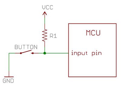
pull up resistor

Image from Sparkfun

What this means is when the button is not pressed, the Arduino reads a logic 1. When the button is pressed, the current flows through the resistor to ground and the Arduino reads a logic 0.

Internal Pull Up Resistor

The Arduino also has internal pull up resistors so you don't necessarily have to add an extra component to your circuit. There are a couple of ways to use this.

You used to have to do it like this:

pinMode(pin, INPUT);           // set pin to input
digitalWrite(pin, HIGH);       // turn on pullup resistors

Now we can do it simply in one line:

pinMode(pin, INPUT_PULLUP);

This enables the 20k pull up resistor on that pin. The input will no longer be floating when the button is not pressed.

Note: This only works when the other end is connected to ground.

2
  • 2
    It's worth noting that the same idea works for pull-down resistors too; i.e. the resistor normally pulls the pin low, but pressing the button brings it high. Obviously it has to be external though, as there's no internal pull-down on standard Arduinos. Commented Feb 19, 2014 at 23:16
  • I dunno if you evencheck arduino stack exchange now but I am unable to understand the pin diagram. I have push button, with one end having 5V, and the other end having my wire connected to arduino and a 20k Ohm resistor which is connected to ground. Still I am getting random value when the button is not pressed. When it is pressed, I always get 1 Commented Apr 16, 2021 at 17:35
1

There are several possible reasons random values are seen at micro controller inputs when connected to switches. Here are two:

  1. Missing pull up or pull down resistor when using a SPST switch.

Micro controller inputs should not be allowed to float. This can lead to unexpected input states. Instead, inputs should be connected to ground or the micro controller's positive voltage supply usually either directly or though a resistor. It is common to use a pull up resistor when using a SPST switch connected to ground. Or a pull down resistor when using a SPST switch connected to the micro controller's positive voltage supply. Not all micro controllers have pull up or pull down resistors built internally. Some only have one or the other. In these cases an external resistor may be required. Some thought should be given to using micro controllers that do have built in pull up or pull down resistors. The actual resistance value of these built in resistors does vary (may not be carefully controlled). This is fine for the majority of cases. However, if a specific value is needed, it may be best if external resistors were used instead.

  1. Long wires between the micro controller and the switch.

Longer wires are more likely to develop unexpected currents due external electrical noise. It is possible wires are long enough and the environment they are in electrically noisy enough to develop currents that will change the voltage across a pull up or pull down resistor. And, in turn, change the value of the micro controller's input. The higher the resistor value the more likely this will happen. However, the lower the resistor value chosen the more power needed when the SPST switch is closed. This is usually a concern when operating on batteries. There are many aspects to mitigating the effects of electrical noise. And will take us off subject. Instead, if long wires are necessary, consider using a "brake-before-make" SPDT switch which will connect the micro controller's input pin directly to ground or the micro controller's positive supply voltage. This will require running 3 rather than 2 wires to the switch.

Last words: Take care not to connect pull up resistors or switches to voltages higher than the micro controller's positive supply voltage! Some Arduino boards regulate higher voltages to lower voltage before supplying power to the micro controller. For instance, an Arduino board that runs from the 5 Volt USB power source may have a micro controller which actually runs at 3.3 Volt. In such a case, use the 3.3 Volts supplied to the micro controller when connecting a pull up resistor or switch.

1
  • Added this answer as the existing answer does not cover long-wires/electrical-noise inducing unexpected results and the use of SPDT switches instead of a SPST switch with a pull up resistor.
    – st2000
    Commented Dec 29, 2023 at 17:32

Your Answer

By clicking “Post Your Answer”, you agree to our terms of service and acknowledge you have read our privacy policy.

Not the answer you're looking for? Browse other questions tagged or ask your own question.