0

I've been teaching a blind student how to program and build electronics with Arduino. So far I've substituted LED's with piezo buzzers with excellent results. We are getting to the point where more complicated output is required and braille displays are excessively expensive. I've found these micro solenoids on eBay. micro solenoids
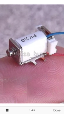
They are 5 volts and small enough to place on a grid to create display. Could I substitute these on a regular LED grid and run it via conventional shift register or MAX7219 methods?

Here is the link to the micro solenoids.

3 Answers 3

0

If I understand Chinglish, you won't be able to drive it with the typical LED drivers... it give 350mA for "Current". That's 30-40 times the normal LED current, and would require special driver circuitry capable of 0.350A * 5 V = 1.75W per device, over 100W to activate all of them!

I think it also says they cannot be continuously activated, which makes sense, given the small package and high power. Leave 'em on long enough and they would probably burn your fingers. :(

6
  • Well that would explain why no one has tried it this way. When no current is running through them they are extended so I already new that Braille "image" would be inverse. I'm going to keep trying to find a less expensive solution to Braille displays (vibration, air puffs, water cooled, etc). Thanks for your help.
    – Gabe Ruiz
    Commented Nov 15, 2015 at 3:28
  • So a 2x3 matrix, the minimum required to display 1 character, it would be 10.5 W? Would the heat be equivalent to a 10 W incandescent bulb?
    – Gabe Ruiz
    Commented Nov 15, 2015 at 3:39
  • 10W, yes... Darn close to an incandescent bulb, except for the small percentage of power it radiates as light. You know, if you have a mechanical aptitude, you might try modifying some "micro vibration motors" used in cell phones (be careful on that spelling :-P), or using geared "micro stepper motor" to lift a rod (rack and pinion). The stepper has a known rotation, unlike the vibration motors.
    – slash-dev
    Commented Nov 15, 2015 at 3:39
  • The micro vibration motors were my next stop. I'll just have to figure out how to isolate the vibration of each motor.
    – Gabe Ruiz
    Commented Nov 15, 2015 at 3:42
  • If you round-over the weight, it might be more like a cam that lifts (jiggles?) a rod. The pics I've seen seem to show that the weight is crimped on to the shaft. Dremel work? The more you take away, the less the travel in the rod. I think a stepper gear (pinion) next to a "toothed" rod (rack) might be worth investigating. See here.
    – slash-dev
    Commented Nov 15, 2015 at 3:47
1

Yes the power requirements are a lot more than LEDs but theres a trick with solenoids which is each solenoid output would be PWM rather than DC.

You could experiment with different frequencies/duties but I reckon start with a 100-200Hz pulse at around 25-50% duty. Can drop your power down by at least a 1/4 or less.

This is obviously a bit more complex than a simple off or on. But solenoids have no problem with holding their magnetic field with a pulse and its recommended to avoid overheating the coil.

Edit: so there are 2 ways to approach it that I see. Either dedicate 1 pin on your micro for each solenoid which would go through a driver (with diode protection) and setup a PWM routine to pulse each output. or.. use a matrix approach with an oscillator on each solenoid. Meaning you would just switch the oscillator on and off

The first approach is more code intensive and would be limited by the micro. The second is more hardware intensive limited by the components you have.

Also to make sure they retract a short reverse polarity pulse would do that.

1
  • 1
    I'd just go with all shift registers. No multiplexing. Next attach a PWM signal to the enable pin of all the registers to bring down the power usage. You probably want to disable the PWM when activating the motion, then a few milliseconds later enable PWM to hold the solenoids in position. As it requires more power to change, than to hold a position.
    – Gerben
    Commented Nov 15, 2015 at 14:52
0

Looking at the description. They have a permanent magnet inside, so they are kind of "latching". So using an H-bridge you can have them move outward or inward.

The only problem will be that a finger will be pushing on the shaft. So unpowered, they will move when a finger goes over them. You would have to add some mechanism that moves another pin, and locks it in place.

2
  • 1
    I have them present and they take quite a bit of pressure to retract when unpowered.
    – Gabe Ruiz
    Commented Nov 15, 2015 at 15:18
  • Never mind, I was wrong. It will retract quite easily.
    – Gabe Ruiz
    Commented Nov 16, 2015 at 20:38

Your Answer

By clicking “Post Your Answer”, you agree to our terms of service and acknowledge you have read our privacy policy.

Not the answer you're looking for? Browse other questions tagged or ask your own question.