3

The Xbee requires a 3.3V power input and the Arduino Pro Mini (5V version) only provides a regulated 5V.

Question: What will be the simplest way to provide a 3.3V rail to the XBee from the Arduino Pro Mini?

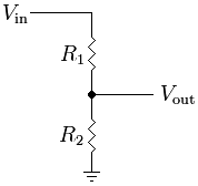
If we use a voltage divider consisting of 2 resistors, the ratio should be 66/100, but how do we choose the resistor values?

If we choose a 3.3V voltage regulator, will the STMicroelectronics L78L33ACZ be suitable?
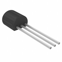
enter image description here

Between the voltage divider and voltage regulator, which is the preferred method? Is there a better alternative?

3
  • 1
    There is a second part to this - does the XBee talk to the Arduino? Connecting a 5v device to a 3.3v device requires a level shifter to protect and interface between the different voltage devices. While both power and IO can be interfaced using simple voltage divider resistors - personally I recommend regulating the 3.3v supply and using a simple MOSFET level shifter for IO. If you update the question for this, I can post a relevant circuit to accomplish both.
    – Ron J.
    Commented May 6, 2014 at 13:08
  • @RonJ. Yes XBee is communicating with Arduino. How can you use the MOSFET level shifter for IO? Will be great if I can have a look at your circuit :)
    – Nyxynyx
    Commented May 6, 2014 at 20:51
  • Is there any particular reason that you need a 5V Pro Mini? If not, then it would be much more appropriate to use a 3.3V Pro Mini in its place. Commented Jan 16, 2017 at 14:57

3 Answers 3

5

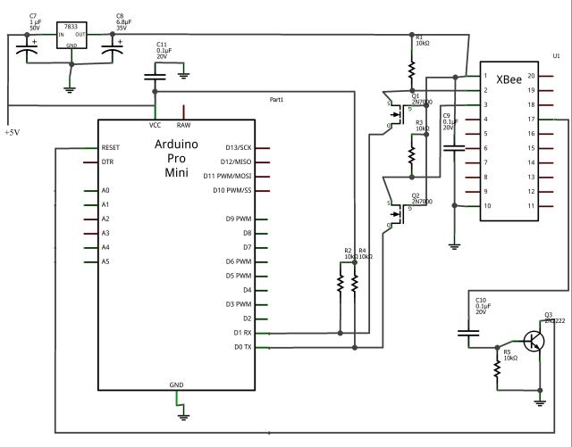
This is part of a Fritzing circuit I used to control the x'mas tree lights (the relays and sensors have been snipped out) with an XBee. This circuit uses a 3.3v LDO you may have to change the capacitor values depending on your regulator specs. I chose to use a separate 5V regulator (not shown) but it will work off the Pro Mini's +5V power rail.

There are two FETs that do the actual level shifting, the bonus transistor allows you to reset the Arduino and thus gives you the ability to program it over the air via the XBee (beyond the scope of the question, but if you want to go wireless, go wireless all the way - do the Google for wireless programming over XBee if needed). Note the 0.1uF across the XBee power pins, I recommend this capacitor be placed as close to the XBee as possible to minimize noise (I solder it across the back of the XBee interface board).

enter image description here

2
  • In what ways can noise across the XBee's power inputs affect it?
    – Nyxynyx
    Commented May 7, 2014 at 17:48
  • @Nyxynyx I don't remember exactly where it was specified, may have been in the XBee datasheet. The XBee is after all a 2.4GHz transceiver, and electrical noise [could] [may] disrupt communications. A 3 cent disc capacitor certainly doesn't hurt things.
    – Ron J.
    Commented May 8, 2014 at 14:11
1

You can use a voltage regulator to get the supply voltage down to 3.3v.

For the Serial Lines, the best way forward is to use a good level convertor like https://www.sparkfun.com/products/11978 from sparkfun.

If you don't want to buy it, you can also make it using a couple of Mosfet's and resistors. Here's the schematic from Sparkfun.

1
  • Please do not link to external content. When the URL become invalid, this answer becomes useless. Commented May 14, 2014 at 11:46
1

The simplest way, as you ask, is probably a resitor-based voltage divider; its main drawback is the waste of energy in the resistors.

enter image description here

To calculate the "best" resistor values, you'll need to know the amount of current needed by the XBee module.

So you have:

  • Vin = 5V
  • Vout = 3.3V
  • Iout = to be determined (check XBee spec sheet for that)

Then you have to resolve the following equations to calculate the resistor values you shall use:

R1 = R2 x (Vin - Vout) / Vout
Iout = (Vin - Vout) / R1 - Vout / R2

These equations simply come from applying Ohm's law and Kirchhoff's circuit laws.

This site calculates the ideal resistor values for you.

For Iout = 100mA, it gives the following values:

  • R1 = 17 Ohm
  • R2 = 33 Ohm

Another simple way is to use a 3.3V zener diode if you have one on hand. You can google for good circuit examples.

Your Answer

By clicking “Post Your Answer”, you agree to our terms of service and acknowledge you have read our privacy policy.

Not the answer you're looking for? Browse other questions tagged or ask your own question.