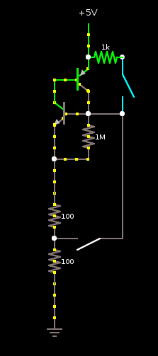
I have made a circuit in the past that does more or less this:

There are two switches in the diagram - the one on the top right turns the circuit on, and the one lower-middle turns it off. Once turned on, it will stay on until the bottom switch is pressed.
The two resistors bottom left, and the switch at the bottom, represent your Arduino.
Note that, this diagram is OUTSIDE the arduino - it provides power TO the Arduino (and any other components relating to your project). That is, the bottom of the 1MOhm resistor, and the bottom of the left transistor, connect to the power pin on the Arduino. Those two resistors don't literally, exist.
It works as follows: The transistors do pretty much all the work. Both transistors work as switches. At the start (as shown in the diagram), both transistors have the same voltage at the base, and the emitter (the top one +5v between top and center/left; the bottom one 0v between center/right and bottom). This turns both switches off, and preserves the status quo, and consuming nearly no power.
As soon as the switch at the top is closed, the base (center/right) of the lower transistor is pulled up to +5V, switches this transistor on, and power can flow from this collector to the emitter. This means power can flow through the TOP transistor from emitter (top) to base (center/left), switching on the TOP transistor. This allows power to flow from the emitter (top) to collector (bottom). This takes over from the pushbutton, keeping the bottom transistor on. This is the other stable state.
At this point, power goes to the Arduino (bottom two resistors, representing load, and bottom switch, which is one of the pins on the Arduino. This pin should be set to "high impedance" until the Arduino wants to switch itself off, then it should go low.
I built the top part of the circuit, with an LED for the bottom half (both switches were just wires), and it worked, but I'd have to consider what would happen if the arduino pin is high or low while the top button is being pressed.

