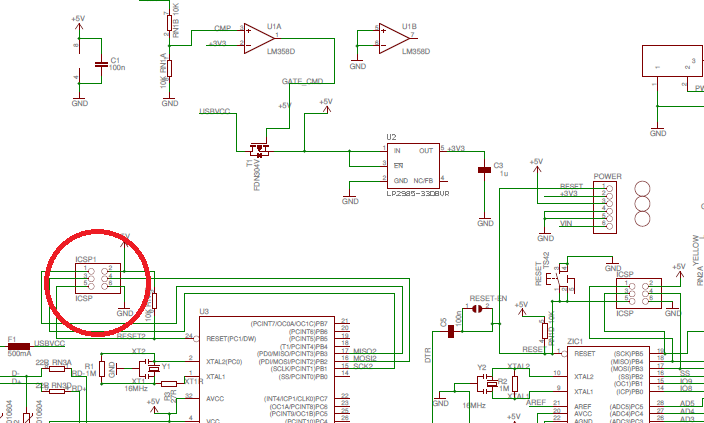
It's for the other MCU on the board.
The main MCU on the Uno is labelled "ZIC1". This is the one that is programmed when you press "Upload" in the IDE. But unlike other Arduinos that use a FTDI chip to connect to the serial port on the main MCU, the Uno uses another MCU instead, labelled "U3" on the left. This MCU runs a small bit of code that acts as a serial port via USB and passes through the bytes to its USART1. This then connects to the USART on the main MCU, where the bootloader on that chip accepts the bytes coming through and writes to flash and EEPROM on the main MCU.
You can use this additional MCU as you would any other, but the only I/O it has available are the USB connection, the SPI connection via its ICSP header, the UART1 connection to both the main MCU and pins 0 and 1, and two LEDs on PD4 and PD5.

