1

Disclaimer: I have asked questions about this project before but this is yet another issue I'm facing.

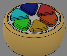
What I really want to do: Build a battery powered device with 6 colored buttons. When you press one of the buttons the gadget should play a sound saying the name of the color.

It should not need an ON/OFF toggle to save battery capacity but rather have a very low idle current draw so that the battery will lasts for weeks (or even months) when it's not used.

Something like this
enter image description here

Hardware: ATtiny85 (low draw in general, very low draw in sleep), DfPlayer, 3.7v Battery (probably 18650)

The 6 buttons are attached to a single input pin. The microcontroller can distinguish them by reading the ADC value. The buttons have different resistors attached to them

How I wanted to do it: My initial plan was to press a button that wakes the microcontroller up. The mcu then wakes the dfplayer, plays a sound and goes back to sleep. If that would not be responsive enough add a delay to the sleep like: if no button was pressed within the last 30s go to sleep. That worked after some initial problems but it turned out that the DfPlayer "sleep mode" doesn't mean it goes to sleep as in it draws less current but much rather that it's just idling, not playing any sound.

How I want to do it now: Pretty much the same as above but instead of sending the DfPlayer to sleep just turn it on and off:
Press a button that wakes the microcontroller up. The mcu then turns the DfPlayer on by setting the gate of an n-channel mosfet (IRF3708) HIGH, waits a short period of time, plays a sound, turns the dfplayer off and goes back to sleep. If that's not responsive enough add a sleep delay like explained above.

What I'm already able to do:

  • make the DfPlayer play a specific sound over serial communication
  • distinguish between the 6 input buttons
  • wake the microcontroller up with any of these buttons
  • turn the DfPlayer on/off by using an n-channel mosfet

The problem that I have: The microcontroller freezes when I set the output pin attached to the mosfet gate to HIGH. Freeze means it just won't execute any code after the digitalWrite(PIN_MOS, HIGH); call. I tested it by turning an LED on a different pin on and off like so

digitalWrite(PIN_LED, HIGH);
digitalWrite(PIN_MOS, HIGH);
digitalWrite(PIN_LED, LOW);

The LED turns on but won't ever turn off. When I use the external reset of the attiny the mosfet will turn off and code will execute again just fine. Until I try to set the mosfet pin to HIGH again.
The DfPlayer will turn on though, I can play sounds on it by shorting 2 pins on it. It doesn't seem to be unstable either. It's just that the attiny hangs up.
I use a cheap lab psu but it should be good enough to be not the problem. I've also tried a fully charged 18650 battery and a CR2032 battery. The 18650 worked the same as the psu and the CR2032 just couldn't handle the draw and the DfPlayer wouldn't properly turn on.
I tried it different voltages between 3.3v and 5v. In theory everything should work and in reality it didn't change anything either.

Here is the breadboard layout I use.
I also added an electrolytic and ceramic cap between Vcc/GND on the DfPlayer but that didn't help either

enter image description here

Here is the code I use

    #include <Arduino.h>
    #include <avr/sleep.h>
    #include <DFMiniMp3.h>
    #include <avr/interrupt.h>
    #include <avr/power.h>
    #include "LemonSerial.h"
    #include "mp3notify.h"
    
    #define PIN_TX PB0
    #define PIN_RX PB1
    #define PIN_MOS PB2
    #define PIN_LED PB3
    #define PIN_A PB4
    
    LemonSerial secondarySerial(PIN_RX, PIN_TX);
    DfMp3 dfmp3(secondarySerial);
    
    void sleep();
    
    void initADC()
    {
      ADMUX =
          (1 << ADLAR) | // left shift result
          (0 << REFS1) | // Sets ref. voltage to VCC, bit 1
          (0 << REFS0) | // Sets ref. voltage to VCC, bit 0
          (0 << MUX3) |  // use ADC2 for input (PB4), MUX bit 3
          (0 << MUX2) |  // use ADC2 for input (PB4), MUX bit 2
          (1 << MUX1) |  // use ADC2 for input (PB4), MUX bit 1
          (0 << MUX0);   // use ADC2 for input (PB4), MUX bit 0
    
      ADCSRA =
          (1 << ADEN) |  // Enable ADC
          (1 << ADPS2) | // set prescaler to 128, bit 2
          (1 << ADPS1) | // set prescaler to 128, bit 1
          (1 << ADPS0);  // set prescaler to 128, bit 0
    }
    
    void setup()
    {
      initADC();
    
      pinMode(PB5, INPUT_PULLUP);
      pinMode(PIN_A, INPUT);
      pinMode(PIN_LED, OUTPUT);
      digitalWrite(PIN_LED, LOW);
      pinMode(PIN_MOS, OUTPUT);
      digitalWrite(PIN_MOS, LOW);
    }
    
    void play(uint16_t track)
    {
      if (digitalRead(PIN_MOS) == LOW)
      {
        digitalWrite(PIN_LED, HIGH);
        delay(500);
        digitalWrite(PIN_MOS, HIGH);
        digitalWrite(PIN_LED, LOW);
    
        delay(500); // wait for DfPlayer to turn on
    
        dfmp3.begin();
        dfmp3.reset();
        dfmp3.disableDac();
        dfmp3.setVolume(30);
        dfmp3.setPlaybackSource(DfMp3_PlaySource_Sd);
      }
    
      dfmp3.playGlobalTrack(track);
    }
    
    void loop()
    {    
      ADCSRA |= (1 << ADSC); // start ADC measurement
      while (ADCSRA & (1 << ADSC))
      {
          // wait till conversion complete
      }
    
      uint8_t adcValue = ADCH;
      // actually calculate the parameter based off adcValue here. omitted for readability
      play(1);
    }
    
    // Interrupt Serviceroutine (Pin-Change-Interrupt)
    ISR(PCINT0_vect)
    {
      LemonSerial::handle_interrupt();
    }
    
    // ADC interrupt service routine
    ISR(ADC_vect)
    {
      ; // noop
    }
13
  • Got a link to the datasheet of the MOSFET you are using?
    – VE7JRO
    Commented Jul 30, 2023 at 22:24
  • @VE7JRO it’s an IRF3708. I’ve attached a link to my post
    – boop
    Commented Jul 30, 2023 at 22:41
  • 1
    You should also have a decoupling capacitor (ceramic say 100nF) directly across the power rails of the ATtiny85 and as physically close as possible to the chip. It is possible that the inrush current to the smoothing capacitor on the SD card player when the mosfet switches on is causing the problem. You may try a 100nf capacitor directly between the mosfet gate and ground and a 10k to 100k resistor between the arduino pin and the gate to slow this switch on. Also search for "attiny85 brown out fuse" . This may be dependent on options provided by the arduino core you are using.
    – 6v6gt
    Commented Jul 31, 2023 at 6:27
  • while (ADCSRA & (1 << ADSC)) { sleepIfIdle(started) ; }. I think it is going to hang in this loop continuously sleeping because the variable started is not refreshed. Try making started global and update it also at the end of your sleep code. If this is the problem then create an answer yourself showing the coding changes.
    – 6v6gt
    Commented Jul 31, 2023 at 7:11
  • Please reduce your sketch to the absolute minimum that stills shows the behavior. Then edit your question and add that code, please. Commented Jul 31, 2023 at 7:32

1 Answer 1

1

@6v6gt was the one who figured out what was missing.

I had to increase the 1Ω resistor between the output pin and gate to 1kΩ and add a 100nF ceramic capacitor between GND and gate. Eventually it worked just as expected.

This is the full code I ended up using. I tried to add enough comments to make it clear what happens.

#include <Arduino.h>
#include <avr/sleep.h>
#include <DFMiniMp3.h>
#include <avr/interrupt.h>
#include <avr/power.h>
// this is just "SoftwareSerial" without blocking interrupts
// thus you have to call handle_interrupt() from here
#include "LemonSerial.h" 
#include "mp3notify.h"

#define PIN_TX PB0
#define PIN_RX PB1
#define PIN_MOS PB2
#define PIN_LED PB3
#define PIN_A PB4
// turning the player on and initializing it takes quite a while
// thus do not go back to sleep immediately after each button press
uint32_t timeoutMs = 30000;
uint64_t started = 0;

// dfplayer api
LemonSerial secondarySerial(PIN_RX, PIN_TX);
DfMp3 dfmp3(secondarySerial);

void sleep();

uint8_t readADC()
{
  ADCSRA |= (1 << ADSC); // start ADC measurement
  while (ADCSRA & (1 << ADSC))
    ; // wait till conversion complete

  uint8_t adcValue = ADCH;
}

void initADC()
{
  ADMUX =
      (1 << ADLAR) | // left shift result
      (0 << REFS1) | // Sets ref. voltage to VCC, bit 1
      (0 << REFS0) | // Sets ref. voltage to VCC, bit 0
      (0 << MUX3) |  // use ADC2 for input (PB4), MUX bit 3
      (0 << MUX2) |  // use ADC2 for input (PB4), MUX bit 2
      (1 << MUX1) |  // use ADC2 for input (PB4), MUX bit 1
      (0 << MUX0);   // use ADC2 for input (PB4), MUX bit 0

  ADCSRA =
      (1 << ADEN) |  // Enable ADC
      (1 << ADPS2) | // set prescaler to 128, bit 2
      (1 << ADPS1) | // set prescaler to 128, bit 1
      (1 << ADPS0);  // set prescaler to 128, bit 0
}

void setup()
{
  initADC();

  // set INPUT_PULLUP to reduce current draw
  pinMode(PB5, INPUT_PULLUP); // PB5 is not assigned to any constant
  pinMode(PIN_LED, INPUT_PULLUP);

  pinMode(PIN_A, INPUT); // ADC pin is physically pulled low
  pinMode(PIN_MOS, OUTPUT);
  digitalWrite(PIN_MOS, LOW);

  started = millis();
}

/// @brief plays a track on the dfplayer. turns the player on if neccessary
/// @param track track number to play
void playTrack(uint16_t track)
{
  started = millis();

  if (digitalRead(PIN_MOS) == LOW)
  {
    digitalWrite(PIN_MOS, HIGH);
    delay(50); // wait 50ms for DfPlayer to turn on

    // baud 4800 because the attiny runs at 16mhz (8mhz -> 9600)
    dfmp3.begin(4800);
    dfmp3.setVolume(30);
  }

  dfmp3.playGlobalTrack(track);
}

void loop()
{
  uint8_t adcValue = readADC();

  if (adcValue >= 227 && adcValue <= 237)
  {
    // 10k ohm (3.0V -> adc 232)
    playTrack(1);
  }
  else if (adcValue >= 212 && adcValue <= 223)
  {
    // 18k ohm (2.8V -> adc 217)
    playTrack(2);
  }
  else if (adcValue >= 196 && adcValue <= 206)
  {
    // 27k ohm (2.6V -> adc 201)
    playTrack(3);
  }
  else if (adcValue >= 181 && adcValue <= 191)
  {
    // 38k ohm (2.4V -> adc 186)
    playTrack(4);
  }
  else if (adcValue >= 165 && adcValue <= 175)
  {
    // 50k ohm (2.2V -> adc 170)
    playTrack(5);
  }
  else if (adcValue >= 150 && adcValue <= 160)
  {
    // 65k ohm (2.0V -> adc 155)
    playTrack(6);
  }
  // ending up here every loop where no button was pressed. so basically 99.99% of the time
  else
  {
    // started gets set to millis() everytime a track is played
    if (millis() - started > timeoutMs)
    {
      // sleep if some time has passed without input (see timeoutMs)
      sleep(); 
    }
  }
}

// sets the device into POWER DOWN mode.you can probably tune it to be more efficient 
void sleep()
{
  digitalWrite(PIN_MOS, LOW);

  // pin change interrupt
  PCMSK |= bit(PIN_A);
  GIFR |= bit(PCIF);  // clear any outstanding interrupts
  GIMSK |= bit(PCIE); // enable pin change interrupts

  set_sleep_mode(SLEEP_MODE_PWR_DOWN);
  power_all_disable(); // power off ADC, Timer 0 and 1, serial interface
  sleep_enable();
  sleep_cpu();
  sleep_disable();
  power_all_enable(); // power everything back on
}

// Interrupt Serviceroutine (Pin-Change-Interrupt)
ISR(PCINT0_vect)
{
  // the SoftwareSerial does not block any interrupt pins anymore and thats why we have to call it from here
  LemonSerial::handle_interrupt();
}

// ADC interrupt service routine
ISR(ADC_vect)
{
  ; // noop
}
This is a schematic from how everything is set up now. This is the first time I drew a real schematic so I hope it's clear whats going on

enter image description here

3
  • The RC network consisting of a 100nF capacitor and a 1k ohm in the gate circuit of the mosfet has a time constant of 100ns. It seems that this is enough to "soften" the switch on of the mini DF player. However, I believe that the extra capacitors you've added (100uF and 100nF) currently between the Vcc and (switched) GND of the player should actually be between Vcc of the player and the main GND otherwise these also have an inrush current when the mosfet is switched on. Why, incidentally, do you consider especially the 100uF capacitor to be necessary ?
    – 6v6gt
    Commented Aug 1, 2023 at 21:02
  • @6v6gt good point. It was just something I found while googling around. Maybe I misunderstood it though. It works without these caps but my understanding was that it helps stabilizing the player. Stabilizing as in: less unwanted noise/crackling
    – boop
    Commented Aug 1, 2023 at 21:32
  • I don't necessarily disagree with the capacitor, more how you have wired it. Have you measured the current when the device is sleeping ? It is more usual to switch modules, in this case the DFplayer, on the high side, that is at their Vcc rather than their Gnd and using an P channel mosfet. The risk of some sort of parasitic powering is higher if the ground side is switched because it is more likely to find an alternative path to ground resulting in some residual current consumption by the module. If the current consumption is small of course you can choose to ignore it.
    – 6v6gt
    Commented Aug 1, 2023 at 22:03

Your Answer

By clicking “Post Your Answer”, you agree to our terms of service and acknowledge you have read our privacy policy.

Not the answer you're looking for? Browse other questions tagged or ask your own question.