3

Arduino | external power supply and USB at the same time

I have got an Arduino Mega 2560 project with many sensor and outputs. Right now I’m supplying it with an external stabilized 5V over the 5V pin (so that I’m using only one power source for all sensor, outputs and Arduino.)

I also have a Raspberry PI connected to the Arduino via USB for flashing and also logging. The Raspberry PI has got an external power supply (and also a board with SSD.)

The problem: If I unplug the RPI external power supply, the Arduino Mega is supplying the RPI with power!!! That’s exactly what I do not want. (Also it’s far too little power for RPI, which isn’t even booting correctly.) Even when I power the Arduino Mega 2560 over the barrel plug (stable 9V), the RPI will be provided with a 5V over the USB cable.

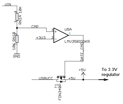
I’m looking in the electrical wiring diagram: I can see the FDN304V The comparison circuit (LM358D) controls this p-channel mosfet FPN340P. But why is it USBVCC connected if the Gate provides 5V over the LM358D?

enter image description here

I saw this interesting articles but I'm a bit confused:

https://arduino.stackexchange.com/questions/893/what-happens-if-i-power-the-arduino-with-both-the-usb-and-external-power-voltage

What happens if I power the Arduino with both the USB and external power voltage simultaneously?

6
  • In previous work coworkers solved this by adding Schottky diode to the cable usb cable. But it's also possible to change 3V3 reg to 1.8 and connect VIN with 5V (It's turning off the mosfet if VIN is 2 times 3V3)
    – KIIV
    Commented Mar 25, 2023 at 18:19
  • get a short USB type A extender and cut the 5 V wire inside the extender cable
    – jsotola
    Commented Mar 25, 2023 at 19:19
  • @jsotola Yes, that was exactly my idea. Actually is very simple in my situation: My RPI is connected with a cable soldered to the usb plug of the Arduino (just because of space problems) -> so I just have to disconnect the 5V pin But I'm more interested in an "professional" solution also I'm very curious why the this circuit with the FDN340P is not working as I thought!
    – stevo
    Commented Mar 26, 2023 at 15:56
  • -KIIV A schottky diode sounds actually nice, but there will be a voltage drop (even when its much less than a normal diode). Probably about 0.2-0.3V which result in a power loss of 90mW @300mA current consumption.
    – stevo
    Commented Mar 26, 2023 at 16:07
  • @stevo the question about the circuit is not about arduino ... it belongs at electronics.stackexchange.com/questions ... anyway, look closely at the MOSFET symbol ... MOSFETs contain a body diode
    – jsotola
    Commented Mar 26, 2023 at 16:18

1 Answer 1

2

Assuming your question is more along the lines of "How to prevent back driving a USB connected RPi through an externally powered Arduino".

Consider cutting the positive power wire in the USB cable connected between the RPi and the Arduino.

As for this specific question:

But why is it USBVCC connected if the Gate provides 5V over the LM358D?

Is it possible you are describing how a N-Channel MOSFET works? The MOSFET in the schematic is a P-Channel MOSFET. The net USBVCC is connected to the net +5V when the P-Channel MOSFET gate is LOW. And is not connected when the gate is HIGH.

1
  • Yes correct, I'm asking exactly this: Why is this circuit powering ("back driving") the USB device. Well I think @jsotola answered already my question: There is a small body diode within this p-channel mosfet which allows current to flow into the USBVCC direction. Yes, I'm disconnecting the 5V pin, that was also my workaround idea. (Actually is very simple in my situation: My RPI is connected with a cable soldered to the usb plug of the Arduino.)
    – stevo
    Commented Mar 26, 2023 at 18:22

Your Answer

By clicking “Post Your Answer”, you agree to our terms of service and acknowledge you have read our privacy policy.

Not the answer you're looking for? Browse other questions tagged or ask your own question.