0

TL;DR

I can read out my heart rate but I have to physically touch GND of the Arduino or else the signal is just noise.

Description

So I've started to play around with an Arduino and wanted to try out a heartrate sensor module (AD8232).

The following is the code I am using for this:

const int CONNECTED_LED = 13;

const int LO_MINUS = 10;
const int LO_PLUS = 11;

bool disconnected = true;

enum State {
  CONNECTED,
  DISCONNECTED,
  LO_MINUS_DISCONNECTED,
  LO_PLUS_DISCONNECTED
};

enum State currentState = DISCONNECTED;


void setup() {
  Serial.begin(9600);
  pinMode(LO_MINUS, INPUT); // Setup for leads off detection LO +
  pinMode(LO_PLUS, INPUT); // Setup for leads off detection LO -
}


void loop() {
  State nextState = getState();

  if (nextState != currentState) {
    // Store the current state
    currentState = nextState;
    switch (nextState) {
      case DISCONNECTED:
        break;
      case LO_MINUS_DISCONNECTED:
        break;
      case LO_PLUS_DISCONNECTED:
        break;
    }
  }

  if (currentState == CONNECTED) {
    digitalWrite(CONNECTED_LED, HIGH);
    Serial.println(analogRead(A0));
  } else {
    digitalWrite(CONNECTED_LED, LOW);
    // Serial.println(-1);
  }

  delay(1);
}

State getState() {
  if (digitalRead(LO_MINUS) == 1 && digitalRead(LO_PLUS) == 1) {
    return DISCONNECTED;
  } else if (digitalRead(LO_PLUS) == 1) {
    return LO_PLUS_DISCONNECTED;
  } else if (digitalRead(LO_MINUS) == 1) {
    return LO_MINUS_DISCONNECTED;
  }
  return CONNECTED;
}

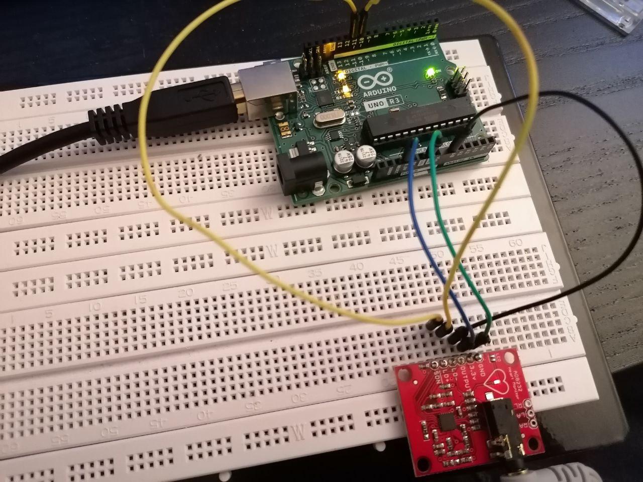
This is how I am connecting the boards (I double checked already twice)

AD8232  | Arduino UNO R3
------------------------
GND     |  GND
3.3v    |  3.3V
OUTPUT  |  A0
LD-     |  ~10
LD+     |  ~11
SDN     |  <not used>

enter image description here

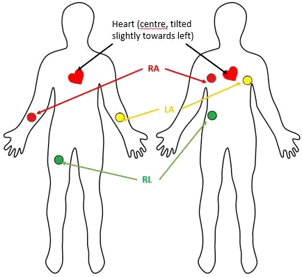
I've followed this diagram for connecting the electrodes:

enter image description here

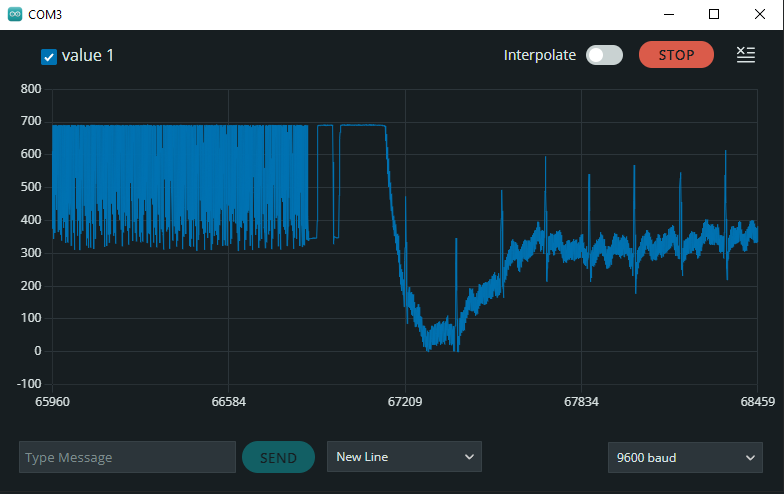
However, the result is a random signal unless I am touching the USB-connector or GND of the Arduino.

Below you can see the random signal and the moment I touched the connector. I noticed this by accident after hitting the reset button after wondering why on earth I only get this random signal:

enter image description here

So.. what's going on here? I have all three electrodes connected.

I've even tried to different modules (I bought the AD8232 two times) but I see the same issues with both modules.

If I touch something else e.g. a radiator (heater) then the signal becomes another kind of random. It only works touching the connector.

Since this appears like a grounding issue I checked for continuity from the GND pin of the AR8232 to the USB connector and continuity is given.

I'm not expert enough (yet) to see the problem. Anybody?

17
  • The Sparkfun tutorial learn.sparkfun.com/tutorials/… links to a sketch which reads also pins 10 and 11 (to detect a lead placement/connection problem) which you are ignoring.
    – 6v6gt
    Commented Dec 28, 2022 at 20:43
  • @6v6gt I have updated my code to the actual thing I am using. Both electrodes appear to be connected (only occasionally I see a disconnect) but most of the time I can read values from A0. It's just that it does not resemple a heartbeat ECG at all. Commented Dec 28, 2022 at 20:50
  • You are powering the module with 3.3 volts ? If you are using a 5 volt Uno, it will see a maximum analog reading of about 675 for peaks in a 3.3 volt signal. There does seem to be some clipping in the top range of the signal.
    – 6v6gt
    Commented Dec 28, 2022 at 21:16
  • Yes, according to those tutorials and the module, the power should be 3.3V. Nothing I see makes sense here. I've tried some sanity checks because I started thinking maybe I killed the Atmega accidentally but basic "LED blinking" is still working fine. I've absolutely no idea what this thing wants from me XD Commented Dec 28, 2022 at 21:48
  • 1
    I am using the ones that came with the module itself. Commented Dec 30, 2022 at 11:04

2 Answers 2

2

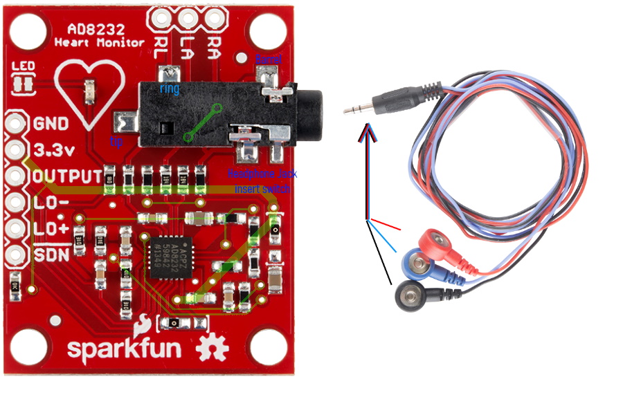
One of your three ECG leads is equivalent to (human)body ground, and it's not making contact. I spent too long making this image to explain it, which should help you a lot more than it will me. I mean, I don't have the board in my hands, so I cannot see which lead goes to which pin. You can, easily, with a multimeter testing for continuity between the: RIGHT ARM, RIGHT LEG, LEFT ARM (RA, RL, LA) solder spots, and the tip, ring, barrel of the jack. Something to keep in mind though is the headphone jack switch. When the plug is physically inserted, this switch opens. Again, I'm not there to guide your multimeter, so this image is the best I can do for you. One of your leads is going to be a grounding lead. It may be the "black" one, it may be the (traditionally) "RL" one, it may be another one, i can't tell.

When you touch USB ground you are effectively replacing the body contact of the missing ground lead. I made these images for you to better understand it. You should be able to fault find this in a few minutes via you MM and continuity testing. combined image of AD8232 with x-ray vision, and leads

4
  • I've tested all three electrodes and I can detect continuity for each of them on the barrel of the jack. I don't think that's the problem. Like mentioned, I have two boards and two sets of electrodes and the issue is the same in both cases. However, is there any chance that it could be the power source? Right now I am powering it via USB cable from my PC. there might be a chance that I have to isolate the sensor and use a battery instead? Commented Jan 2, 2023 at 12:02
  • I can detect continuity for each of them on the barrel of the jack erm... so.... all three electrodes are shorted to the barrel when plugged into the jack? If that's the case you need to re-read what I wrote to you. Commented Jan 3, 2023 at 9:37
  • No, what I meant was RL, LA and RA are connected. The cables are fine. Commented Jan 3, 2023 at 14:36
  • I can't be any more helpful to you. The information you need is presented, and I cannot possibly be there to do it for you. Commented Jan 5, 2023 at 3:27
1

Make sure you unplug the PC charger. I unplugged it and the module then worked fine for me as shown in this video Here

Your Answer

By clicking “Post Your Answer”, you agree to our terms of service and acknowledge you have read our privacy policy.

Not the answer you're looking for? Browse other questions tagged or ask your own question.