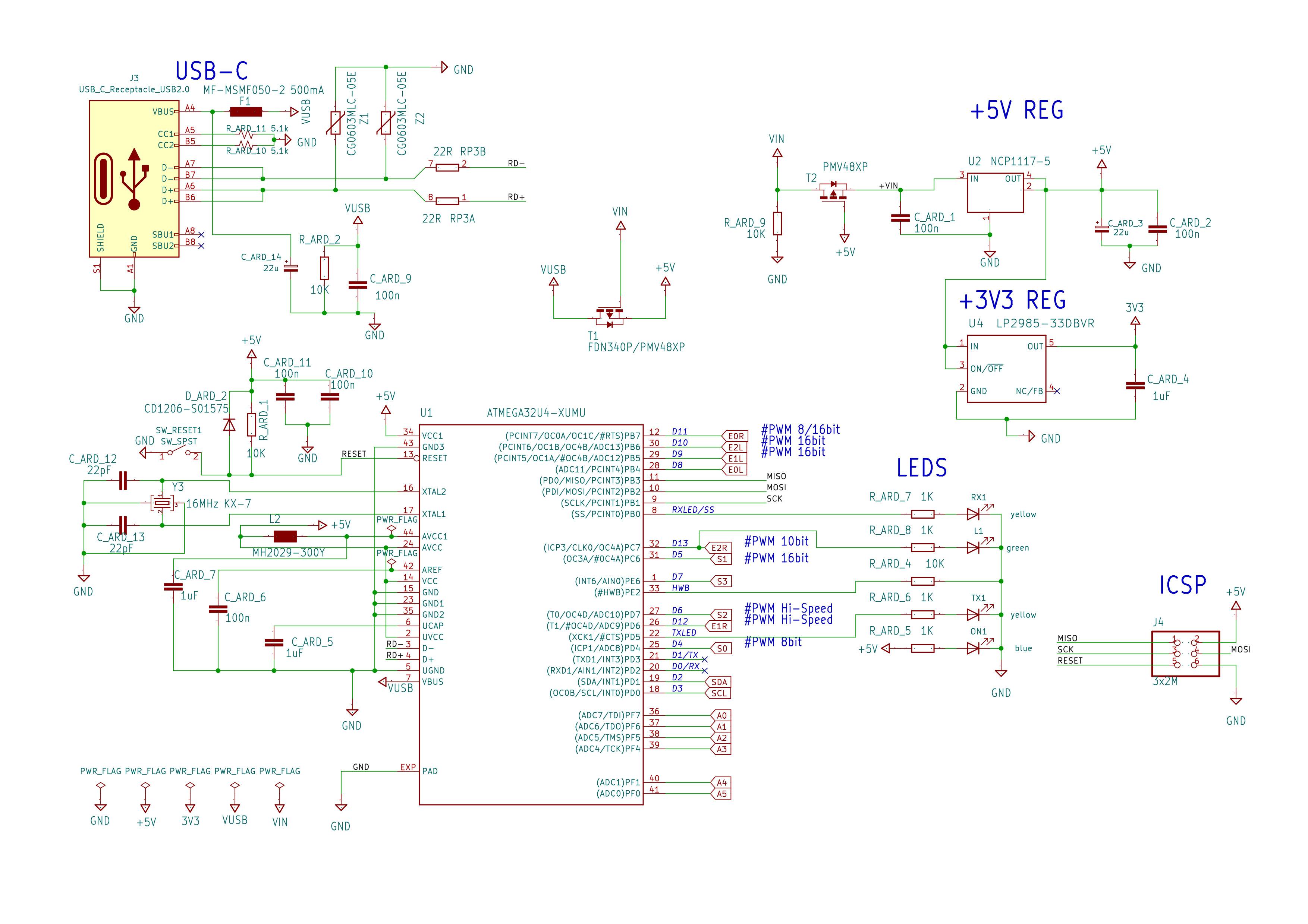
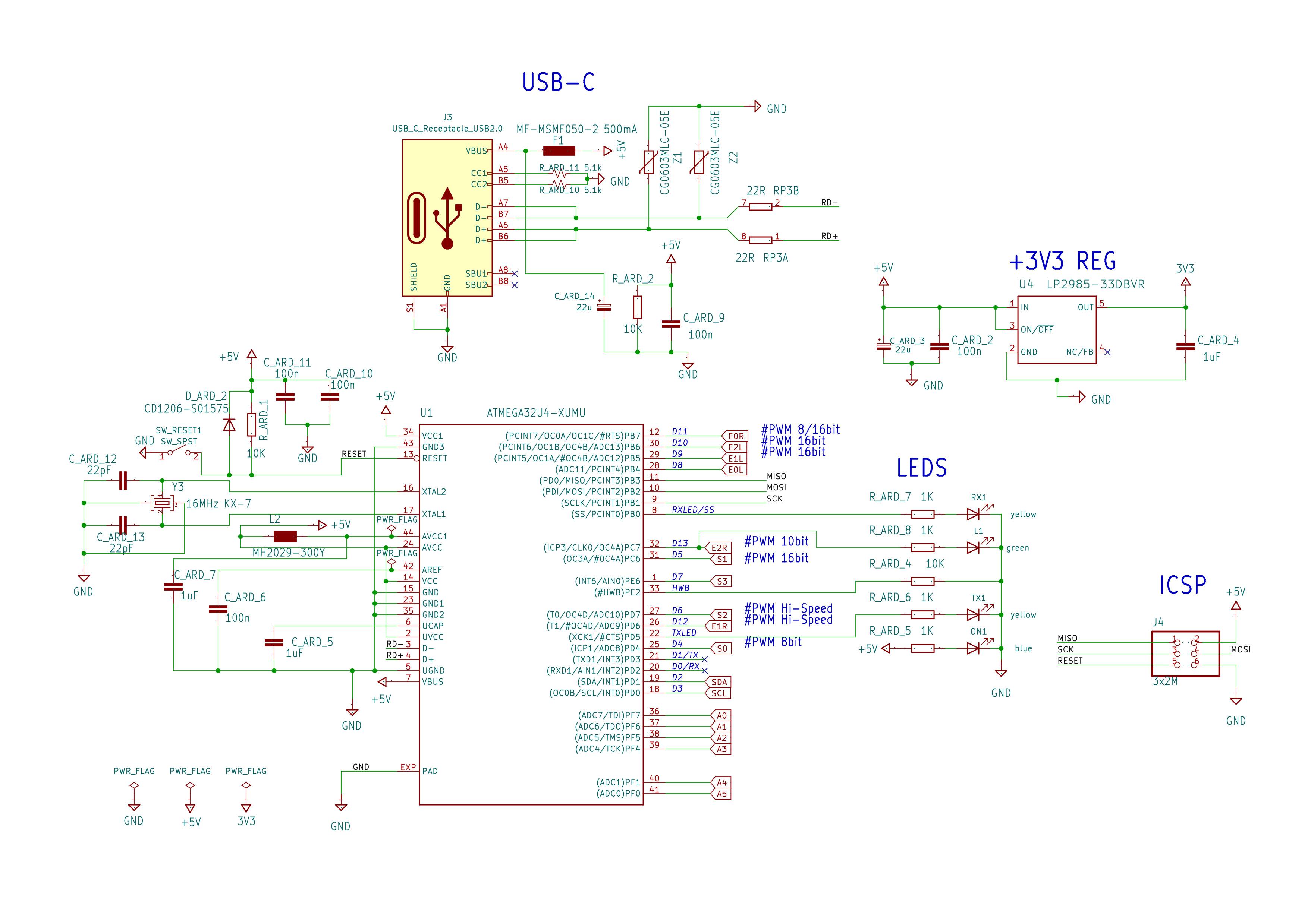
I designed and printed a PCB for my MIDI controller project with a modified Arduino Micro microcontroller essentially built into the design. I swapped out the USB Micro for a USB-C type port (just using the 2.0 protocol). Although I can program the board via ICSP, including getting it to run my Arduino sketches (which I have tested by having it light up the LEDs in a certain pattern, which works as expected), and the fact that it receives power via USB, the problem is that I cannot get the device to connect to my PC over USB - it is not recognized as a USB device, and cannot seem to send or receive data over USB. I'm not sure if I've done something wrong in the design or if I am simply missing something, but could use some advice, as in order to function as intended, the board will need to be able to communicate over USB.
I have tested with various USB-A to USB-C cables and USB-A to Micro cables (tested with other Arduinos) and a Micro to USB-C adapter.
As per various instructions I found online, I connected pull-down resistors of 5.1k Ohms to CC1 and CC2, left SBU1 and SBU2 unconnected as I was planning to use 2.0 protocols to keep things simple (as a related question, can these actually be used to make use of 3.0+ protocols in a design like this with an ATMEGA32U4? Would this be considered better practice in this case and potentially bypass the error?), and wired up D- and D+ as shown in the schematic below; with a EZJZ0V500AA Varistor between each and GND and running through a 4D03WGJ0220T5E Resistor network (which I don't know much about, including whether this type of component has any polarity? I simply tried to follow how the same sort of component was used in the official Arduino Micro schematics) and finally into pins 3 and 4 of the ATMEGA32U4.
This is the original schematic of the board as it was assembled, but as a result of some power issues with this same board which I have since sorted out with help in a separate post Why wont my custom Arduino-Micro-based board receive power via USB?, I had to bypass the 5V regulator and just use VUSB as +5V, so I will put the updated schematic reflecting these changes below the original (I wouldn't think it would affect this issue, but I'm not that experienced and want to err on the side of providing as many details as possible)
Components:
| Designator                                             | Value                   | Component                |
|:--------------------------------------------------------|:-------------------------|:--------------------------|
| C_ARD_1, C_ARD_2, C_ARD_6, C_ARD_9, C_ARD_10, C_ARD_11 | 100n                    | CL05B104KO5NNNC          |
| C_ARD_3, C_ARD_14                                      | 22u                     | RVT22UF16V67RV0017       |
| C_ARD_4, C_ARD_5, C_ARD_7                              | 1uF                     | CL05A105KA5NQNC          |
| C_ARD_12, C_ARD_13                                     | 22pF                    | 0402CG220J500NT          |
| D_ARD_2                                                | CD1206-S01575           | CDSU4148-HF              |
| F1                                                     | MF-MSMF050-2 500mA      | MF-MSMF050-2             |
| J3                                                     | USB_C_Receptacle_USB2.0 | KH-TYPE-C-16P            |
| L1                                                     | green                   | 19-217/GHC-YR1S2/3T      |
| L2                                                     | MH2029-300Y             | BLM21PG300SN1D           |
| ON1                                                    | blue                    | 19-217/BHC-ZL1M2RY/3T    |
| R_ARD_1, R_ARD_2, R_ARD_4, R_ARD_9                     | 10K                     | 0402WGF1002TCE           |
| R_ARD_5, R_ARD_6, R_ARD_7, R_ARD_8                     | 1K                      | 0402WGF1001TCE           |
| R_ARD_10, R_ARD_11                                     | 5.1k                    | 0402WGF5101TCE           |
| RP3                                                    | 22R                     | 4D03WGJ0220T5E           |
| RX1, TX1                                               | yellow                  | 19-213/Y2C-CQ2R2L/3T(CY) |
| T1                                                     | FDN340P/PMV48XP         | PMV48XP                  |
| T2                                                     | PMV48XP                 | PMV48XP                  |
| U1                                                     | ATMEGA32U4-XUMU         | ATMEGA32U4-MU            |
| U2                                                     | NCP1117-5               | NCP1117ST50T3G           |
| U4                                                     | LP2985-33DBVR           | LP2985-33DBVR            |
| Y3                                                     | 16MHz KX-7              | 3225-16.00-10-10-10/A    |
| Z1, Z2                                                 | CG0603MLC-05E           | EZJZ0V500AA              |


