I'm doing a project which is essentially a lighted cube, that communicates status through different colors, where I get this ides [it][1] (having code). So when the light goes below a certain level it turns a certain color, when temp goes above a certain level it turns another color, etc. I'm figuring I'll probably need anywhere from 2 to 4 LEDs per color to get a nice intensity, and the colors would breathe, which is pretty easy with PWM on the arduino.
What I'm thinking is that I'm going to leave all the colors in phase. So that the intensity ramp on red is the same as yellow, is the same as green, etc. That would require only a single PWM output and most importantly, a single section in the code, which would make writing easier.
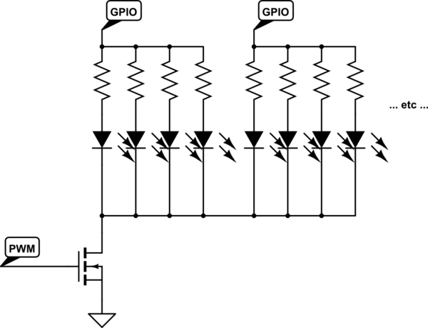
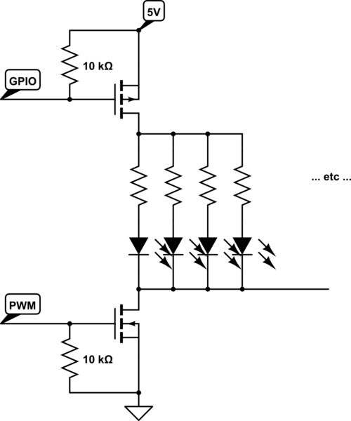
The solution I've come up with is to have the PWM pin drive a MOSFET, and give it the modulation, and the MOSFET would repeat the "breathing" pulse to all the LEDs. Then each color gets switched on or off through a transistor by other pins on the arduino that simply go high or low.
I figure an IRF630, which has an insanely high drain current for this purpose should be more than enough for whatever I might plug into it. And for the switching of each color, maybe an N2222, 4 LEDs will go at about 80 mA max anyway.
So, why not just drive each color from a PWM output? Any thoughts on the circuit? Sound like it could work?
[1]: https://www.kynix.com/Blog/Arduino-Complete-Guide-for-Beginners-with-Examples.html Code Source


