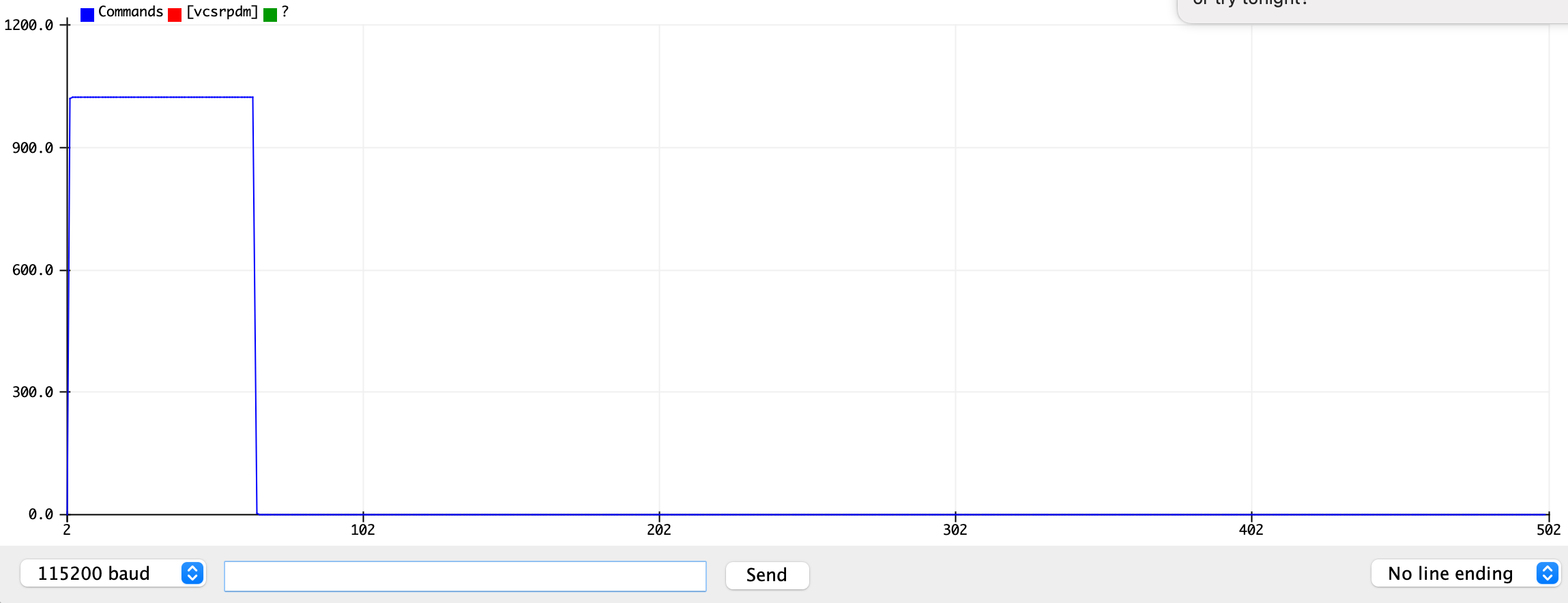
After some bumbling around, several bit are important:
ADCSRA &= ~(bit(ADATE) | bit (ADSC) | bit (ADIE)); // Disable

ADCSRA |=   bit(ADATE) | bit (ADSC) | bit (ADIE); // Enable
The interrupt enable bit bitClear(ADCSRA,ADIE) & bitSet(ADCSRA,ADIE), would stop the current ADC measurement from triggering an interrupt event.
The auto-trigger enable bit bitClear(ADCSRA,ADATE) & bitSet(ADCSRA,ADATE), triggers a new conversion as soon as the current one finishes.
The start conversion bit bitClear(ADCSRA,ADSC) & bitSet(ADCSRA,ADSC), is important for kicking off the first conversion.
The ADC enable bit bitClear(ADCSRA,ADEN) & bitSet(ADCSRA,ADEN), turns the ADC subsystem on and off, but there is a bit of a delay on start up.
Ultimately I left free-running automatic ADC enabled and switched the data recording on and off using the ADCSRA&bit(ADIE) as a "BURST" state variable. I think this is good enough for generic impulse-response testing:
//: ArduinoPulseADCSample.ino -- Pulse a pin and sample response on ADC
// For Arduino Uno/Nano/mega
// https://github.com/drf5n/foxyPulseInduction_Discrimination/tree/discrimination/ArduinoPulseADCSample
// Adapted from  http://www.gammon.com.au/forum/?id=11488&reply=5#reply5
//          and https://github.com/pedvide/ADC/tree/master/examples/analogContinuousRead
//
// This code emits a digital pulse on A1 and collects a sample of highspeed ADC from A0
// It sets up a free-running ADC to quickly record a set of ADC data in
// response to the pulse.  The size of the pulse, pins, number of samples,
// speed of sampling, etc... are all configurable.
// The ADC interrupt handler controls the pulse length and filling the sample buffer
//
// Serial Commands:
//
//  *  Write v and press enter on the serial console to get the value
//  *  Write c and press enter on the serial console to check that the conversion status,
//  *  Write s to stop the conversions, you can restart it writing r.
//  *  Write r to restart the conversions.
//  *  Write p to emit a pulse and record a burst of values
//  *  Write d to see the data recorded during the burst (compatible with SerialPlotter)
//  *  Write m to see metadata about the sample size and interval
//
//  Loopback test with a jumper or RC network between A1 and A2.
//

// Configurables:
const byte adcPin = 0; // A0 -- Pin to read ADC data from
const byte pulsePin = A1; // Next to A0 -- pin to pulse
const byte oneshot_pin = 12; // OC1B pin on Mega, controlled by Timer1
const int pulse_us = 50; // pulse duration
const int numSamples = 20; // sample set
// Change the sampling speed with the prescaler config in setup()


volatile uint16_t samples[numSamples];
volatile int sample = 0;    // position in sample state variable
#define BURST (ADCSRA & bit(ADIE)) /* Sampling burst state variable */
int adcReading;
unsigned long sampleEnd;
unsigned long pulseStart, pulseEnd;


// ########## Timer1 One-shot functions
// The one shot pulses are output on Digital pin OC1B (Arduino Uno D10, Mega D12, Nano D3)
// Modified by Dave Forrest 2020-01-11 for Timer 1
// Based on Josh Levine's Nov 23, 2015 work at https://github.com/bigjosh/TimerShot/blob/master/TimerShot.ino

// Setup the one-shot pulse generator and initialize with a pulse width that is (cycles) clock counts long
#define OSP_SET_WIDTH(cycles) (OCR1B = 0xffff-(cycles-1))
void osp_setup(uint16_t cycles) { // 1 idles, 0xffff never matches, 2-0xfffe makes pulses
  const byte prescaler = 0b010; // Choose /8 for 0.5us resolution
                                // 0b001: /1,      16MHz, 62.5ns resolution, 4ms max
                                // 0b010: /8,       2MHz,  0.5us resolution, 32ms max
                                // 0b011: /64,    250kHz,  4us  resolution, 263ms max
                                // 0b100: /256,  62.5kHz  16us  resolution, 1.048s max
                                // 0b101: /1024, 15625Hz, 64us  resolution, 4.194176s max
  TCCR1B =  0;      // Halt counter by setting clock select bits to 0 (No clock source).
  // This keeps anyhting from happening while we get set up
  TCNT1 = 0x00;     // Start counting at bottom.
  OCR1A = 0;      // Set TOP to 0. This effectively keeps us from counting because the counter just keeps resetting back to 0.
  // We break out of this by manually setting the TCNT higher than 0, in which case it will count all the way up to MAX and then overflow back to 0 and get locked up again.
  OSP_SET_WIDTH(cycles);    // This also makes new OCR values get loaded frm the buffer on every clock cycle.
  TCCR1A = 0b11 << COM1B0  | 0b11 << WGM10; // OC1B=Set on Match, clear on BOTTOM. Mode 15 Fast PWM.
  TCCR1B = (0b11 << WGM12) | (prescaler << CS10); // Start counting now. WGM 15=0b1111  to select Fast PWM mode
  // Setup the OC1B pin for one-shot output:
  //DDRB |= _BV(2);     // Uno Set pin to output (Note that OC1B = GPIO port PB2 = Arduino Uno Digital Pin 10)
  DDRB |= _BV(6);     // Mega Set pin to output (Note that OC1B = GPIO port PB6 = Arduino Mega Digital Pin 12)
  //DDRD |= _BV(3);     // Nano Set pin to output (Note that OC1B = GPIO port PD3 = Arduino Nano Digital Pin 3)
}

// Setup the one-shot pulse generator to idle:
void osp_setup() {
  osp_setup(1);  // 1 puts it in idle mode, 0xffff never triggers, 2-0xfffe produces pulses.
}

// Macro to Fire a one-shot pulse. Use the most recently set width.
#define OSP_FIRE() (TCNT1 = OCR1B - 1)

// Macro to Test there is currently a pulse still in progress
#define OSP_INPROGRESS() (TCNT1>0)

// Macro to Fire a one-shot pulse with the specififed width.
// Order of operations in calculating m must avoid overflow of the unint16_t.
// TCNT2 starts one count lower than the match value because the chip will block any compare on the cycle after setting a TCNT.
#define OSP_SET_AND_FIRE(cycles) {uint16_t m=0xffff-(cycles-1); noInterrupts();OCR1B=m;TCNT1 =m-1;interrupts();}

// ##########  End of Timer1 One-shot functions
ISR(TIMER1_OVF_vect) { //When overflow...
  //  OCRA1=ICR1; // Constant off in WGM 14, COM1A1:0==0b11
  TCCR1B &= ~(0b111 << CS10) ; //turn off clock
}

//######### ADC Bit-bang for free-running capture of A0
void adc_setup_freerunning(const byte adcPin){
  // set the analog reference (high two bits of ADMUX) and select the
  // channel (low 4 bits).  this also sets ADLAR (left-adjust result)
  // to 0 (the default).
  ADMUX = bit (REFS0) | (adcPin & 0x07);

  // Set the ADC ADPSx prescaler flags to control sampling speed/accuracy
  ADCSRA &= ~(bit (ADPS0) | bit (ADPS1) | bit (ADPS2)); // clear prescaler bits

  //ADCSRA |= 0b001 << ADPS0;   //   2    5 bit,
  //ADCSRA |= 0b010 << ADPS0;   //   4    6 bit, 5.36us
  //ADCSRA |= 0b011 << ADPS0;   //   8    9 bit, 6.51us
  ADCSRA |= 0b100 << ADPS0;   //  16   10 bit, 13us
  //ADCSRA |= 0b101 << ADPS0;   //  32     10 bit, 26us
  //ADCSRA |= 0b110 << ADPS0;   //  64     10 bit, 52us
  //ADCSRA |= 0b111 << ADPS0;   // 128     10 bit, 104us

  //enable automatic conversions, start them and interrupt on finish
  //ADCSRA |= bit(ADATE) | bit (ADSC) | bit (ADIE);
    ADCSRA |= bit(ADATE) | bit (ADSC) ;

}

void setup ()
{
  Serial.begin (115200);
  //pinMode(pulsePin, OUTPUT);
  osp_setup(); // Config Mega Digital 12 for oneshot output
  adc_setup_freerunning(adcPin);

}  // end of setup

// ADC complete ISR
ISR (ADC_vect)  // Store ADC burst values
{
  if (sample >= numSamples) // watch off-by-one
  {
    ADCSRA &= ~bit(ADIE);  // end of sampling burst so stop interrupting
    return;
  }
  // Handle samples
  samples[sample++ ] = ADC;
  //if ( sample == 0){
   // OSP_SET_AND_FIRE(pulse_us * 2); //
  //}
}  // end of ADC_vect

void loop ()
{
  char c;
  char buff[80];
  unsigned long sampleDuration;
  unsigned long pulseDuration;
  // if last reading finished, process it

  // if we aren't taking a reading, start a new one

  if (Serial.available()) {
    c = Serial.read();
    switch (c) {
      case 'c': // Converting?
        Serial.print("ADCSRA: ");
        Serial.println(ADCSRA, BIN);
        break;
      case 's': // stop conversions
        ADCSRA &= ~(bit (ADSC) | bit (ADIE));
        break;
      case 'r': // restart conversions
        ADCSRA |= bit (ADSC) | bit (ADIE);
        break;
      case 'v':
        adcReading = ADC;
        Serial.print(adcReading);
        Serial.print(' ');
        Serial.print((0.5 + adcReading) * 5.0 / 1024, 4);
        Serial.println(" V");
        break;
      case 'm':
        {
          unsigned long sampleDuration = sampleEnd - pulseStart;
          unsigned long pulseDuration  = pulseEnd - pulseStart;

          Serial.print("# Pulse: ");
          Serial.print(pulseDuration);
          Serial.print("us and ");
          Serial.print(numSamples);
          Serial.println(" samples.");
          Serial.print("# Time: ");
          Serial.print(sampleDuration);
          Serial.print("us burst of ");
          Serial.print(numSamples);
          Serial.print(" samples at ");
          Serial.print(1.0 * (unsigned long)(sampleEnd - pulseStart) / numSamples);
          Serial.println("us/sample");
          sprintf(buff, " sampleEnd, pulseEnd, pulseStart %02lu : %02lu : %02lu \n", sampleEnd, pulseEnd, pulseStart);
          Serial.print(buff);
          break;
        }
      case 'p': // start pulse
        sample = 0;  // reset sample SV
        pulseStart = micros();
        OSP_SET_AND_FIRE(pulse_us * 2); // pulse outside ISR
        ADCSRA |= bit(ADIF) | bit(ADIE); // clear existing ADInterruptFlag and enable ADC Interrupts
        while(BURST); // block until burst done
        sampleEnd = micros(); // Record times
        pulseEnd = pulseStart + pulse_us;
        break;
      case 'D':
      case 'd': {// report Data
          sampleDuration = sampleEnd - pulseStart;
          for (int ii = 0 ; ii < numSamples ; ii++) {
            if (c == 'D') {
              Serial.print(ii * sampleDuration / numSamples);
              Serial.print(' ');
            }
            Serial.println(samples[ii]);
          }
        }
        break;
      case ' ':
      case '\n':
      case '\r':
        break;
      case 'h':
      case '?':
      default:
        {
          Serial.println("\nArduinoPulseADCSample.in -- Pulse A1 and read a burst of samples from A0\n"
                         "based on serial commands");
          Serial.println("# https://github.com/drf5n/foxyPulseInduction_Discrimination/tree/discrimination/ArduinoPulseADCSample\nCommands: [vcsrpdm] ?");
          Serial.println("Commands:\n"
                         "p: Pulse -- Start a pulse cycle on A1 and record data on A0\n"
                         "d,D: Data -- Dump the data from the last pulse\n"
                         "m: Metadata -- Print the length of pulse, number of samples and rate\n"
                         "v: Voltage -- Conver voltage on A0\n"
                         "c: Converting? -- show ADCSSRA register\n"
                         "h?: Help -- Print this\n"
                        );
        }
        break;
        ;;
    }
  }

  // do other stuff here

}  // end of loop
This is the output from the p,m,d commands with a jumper connecting pin 12 to A0 with the /16 prescaler:
# Pulse: 50us and 20 samples.
# Time: 276us burst of 20 samples at 13.80us/sample
 sampleEnd, pulseEnd, pulseStart 19270968 : 19270742 : 19270692
0
1020
1023
1023
1023
3
0
0
0
0
0
0
0
0
0
0
0
0
0
0
And again with the /8 prescaler. 7.2us/sample or 139Ksamples/sec for 8-9bits isn't bad:
# Pulse: 50us and 20 samples.
# Time: 144us burst of 20 samples at 7.20us/sample
 sampleEnd, pulseEnd, pulseStart 4229952 : 4229858 : 4229808
0
792
1020
1022
1022
1020
1022
1022
1022
305
3
0
0
0
0
0
0
0
0
0

ArduinoPulseADCSample.in -- Pulse A1 and read a burst of samples from A0
based on serial commands
# https://github.com/drf5n/foxyPulseInduction_Discrimination/tree/discrimination/ArduinoPulseADCSample
Commands: [vcsrpdm] ?
Commands:
p: Pulse -- Start a pulse cycle on A1 and record data on A0
d,D: Data -- Dump the data from the last pulse
m: Metadata -- Print the length of pulse, number of samples and rate
v: Voltage -- Conver voltage on A0
c: Converting? -- show ADCSRA register
h?: Help -- Print this

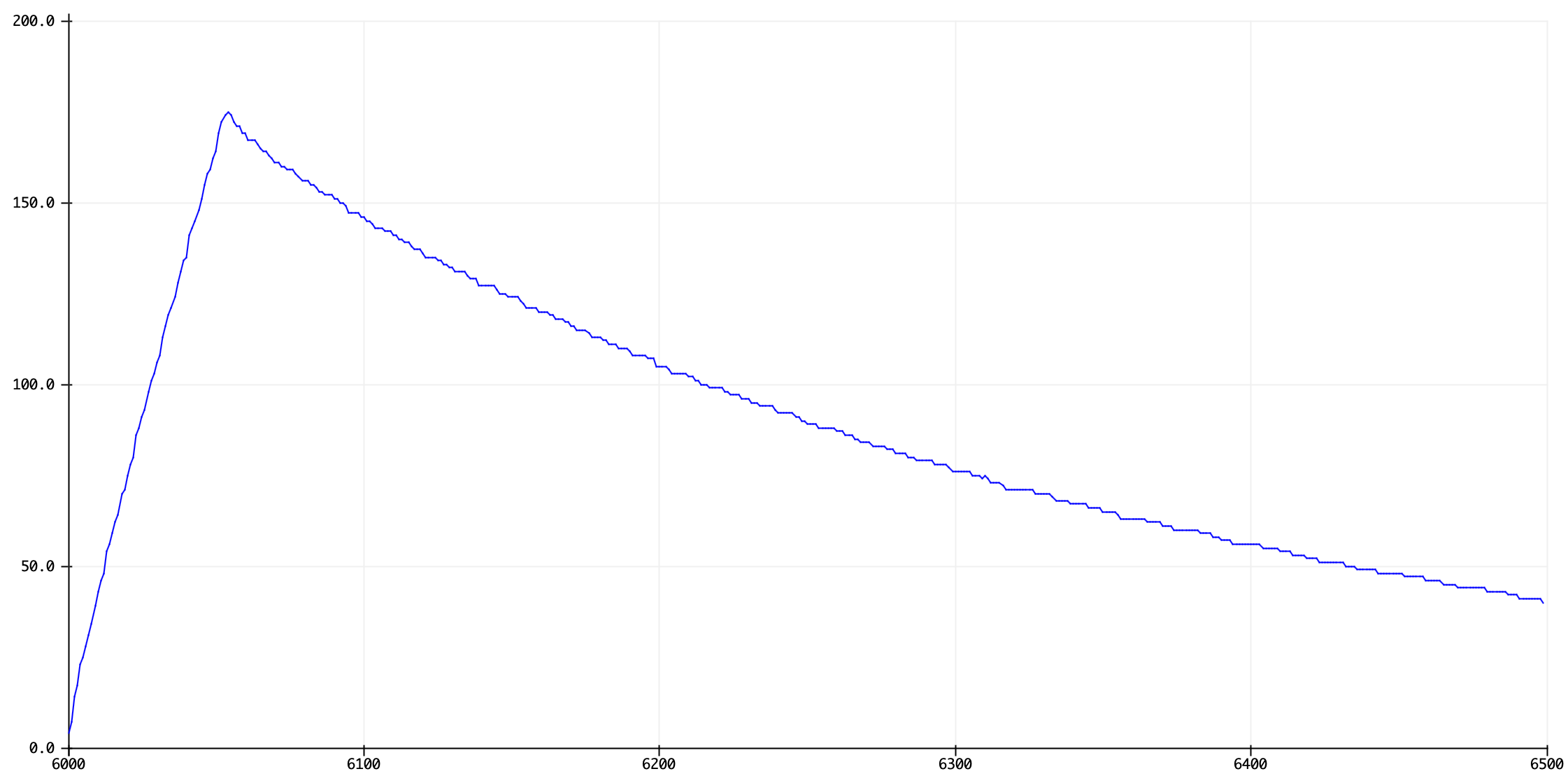
Here's an R-C pulse-decay trace on the Serial Plotter with a 22K resistor across A0&12 and a 22uF capacitor from GND to A0.


sampleback to zero, when you want to start recording a new set of measurements.