A photoresistor is already a resistor and will limit the voltage in the circuit. Why can't this be connected to a pin and measured? Why is a second resistor needed to connect the photoresistor to ground?
6 Answers
The simple answer is that voltage is very easy for the Arduino to measure, while resistance is not, and most sensors such as Photoresistor (LDR), flex sensor, thermistors and more - are actually a variable resistors.
The main reason it's hard to measure resistance changes is that the Arduino (and most IC) contain a tiny system called Analog to Digital Converter (ADC). This system translates changes in analog voltage to a series of 1's and 0's that can be in turn converted to an Integer for example.
The ADC is designed to read voltage changes, and if we want to use the Arduino's analogRead (which utilizes the ADC) to get the Photoresistor readings for example, we will need a way to convert the changes in resistance to changes in voltage - and a voltage divider is the easiest way to do it.
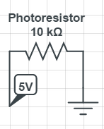
It is true that the sensor is already a resistor, and as such it should change the voltage across it. But you would have trouble measuring the voltage changes, since there is no reference point except for Vcc (5V) and Ground:

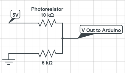
In contrary, when using a voltage divider, you have a well defined reference point to measure the voltage changes:

This isn't strictly an Arduino question, but I appreciate that things like photo-resistors are common early projects for Arduino users.
Resistors (and other components) don't really limit the voltage in the circuit as such. Rather, each component in a series circuit gets a proportion of the total voltage. That proportion is determined by its resistance.
If you only have one component, then the entire voltage is dropped across it no matter what resistance it has. Changing the resistance in that situation would only affect the amount of current flowing through it.
You need the second resistor as a fixed reference point. You know how much voltage it will get if both resistances are equal, and that the relationship between voltage and resistance is (hypothetically) linear. You can therefore use that to figure out what resistance the other component has, e.g. the photo-resistor.
As a side note, the second resistor can also play an important role for safety. Without it, you could potentially end up with a short-circuit if the other component's resistance goes too low.
-
"would only affect the amount of current" - I think this is incorrect, like the case where you use a resistor next to a LED to drop the voltage. Also, A2D are high impedance, and low resistance shouldn't cause short-circuit.– OmerCommented Jan 9, 2015 at 12:07
-
2@Omer "If you only have one component...". A resistor and LED together are two components. :) You're right that a short-circuit isn't an issue for a typical A2D, but that's not the only situation where you might want to use a photo-resistor or similar. Commented Jan 9, 2015 at 12:14
-
Accurate measurement of resistance requires a precise current source (http://www.digikey.com/product-search/en/integrated-circuits-ics/pmic-current-regulation-management/2556448?k=current%20source).
Ohm's law, V=IR or R=V/I states that for linear components, the value of resistance in the circuit can be estimated by the ratio of the applied voltage divided by the current. With a simple voltage divider, as the resistance of the sensor changes so does the current in the circuit. So measuring the voltage at the junction does not necessarily provide an accurate indication of the current in the circuit. Both the imposed voltage and current should be controlled to obtain accurate measurements.
also another big reason for it is if you have just in series, a power source, an LDR and say a bulb, then the bulb may come on as soon as the LDR resistance gets low enough, then it will get brighter as the resistance keeps decreasing. If configured with more resistors in a potential divider with a transistor and the bulb at the collector side, then you can vary the resistors to define the exact amount of light that will allow approx 1.6V (?)(whatever voltage turns the base into a conductor anyway), and therefore the light at which the bulb will suddenly turn on with a constant power supply direct from the power source through a fixed resistor if needed.
So in series an LDR will vary the current with light around the circuit, in a divider and transistor it functions as a light dependant switch
Unlike other electric components, a photoresistor(or light-dependent resistor,LDR,or photocell) is a variable resistor. This means its resistance can depend according to light intensity.
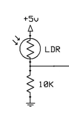
I will go first with half of the circuit diagram to understand clearly.
The resistance of a photoresistor decreases with increasing light intensity. Strong Light —> LDR resistance(decreases to 0ohms) So the 10k(ohm) resistor sees closer to 5V.
The resistance of a photoresistor increases with decreasing light intensity. Dim Light —>LDR resistance(increases to infinity).
So, the 10k(ohm) resistor only gets a little voltage.
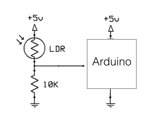
Here is the full circuit diagram that you want to ask why second resistor is needed.
The key point is Arduino board also has Vcc(5V) and ground. So, there is no current if the potential difference is zero. Therefore, firstly, Vcc(5V) will flow through the photoresistor and go to the 10k(ohm) resistor.
Then, since there is a parallel circuit, arduino will get the same voltage as the 10k(ohm) resistor. So this LDR resistor does the function of a pull-up resistor which draws the current to VCC.
I THINK NONE OF THE ABOVE ANSWERS ARE CLEARLY DEFINING THE SOLUTION. I WILL ANSWER WITH RESPECT TO THE WORKINGS OF AN LDR CIRCUIT WITH A LIGHT BULB THAT SWITCHES ON IN THE DARK AND OFF IN LIGHT.
LETS ASSUME THAT WE HAVE AN LDR ONLY CONNECTED IN SERIES TO A LIGHT BULB. THE LDR IS ALREADY ACTING AS A VARIABLE RESISTOR AND HENCE WILL ALLOW CURRENT TO FLOW IN THE PRESENCE OF LIGHT, (LIGHT INTENSITY BEING DEPENDANT ON THE CURRENT RESISTANCE) AND WILL LIMIT THE CURRENT WHEN IT IS DARK. THIS MEANS THAT THE BULB LIGHTS UP IN LIGHT AND IS OFF WHEN IT IS DARK. THERE IS NO PRACTICAL USE FOR THIS. I WANT THE BULB TO LIGHT IN THE DARK AND SWITCH OFF IN THE PRESENCE OF LIGHT.
SO WHAT I DO IS ADD A RESISTOR IN SERIES TO THE LDR. THIS RESISTOR HAS A FIXED RESISTANCE MUCH LOWER THAN THE LDR AT ITS HIGHEST RESISTANCE BUT MUCH HIGHER THAN THE LDR AT ITS LOWEST RESISTANCE. THE BULB ELECTRIC PATH IS CONNECTED BETWEEN THE LDR AND THE RESISTOR. PLEASE NOTE THAT THE RESISTOR IS PLACED ABOVE THE LDR.
NOW LOOK AT IT IN TERMS OF CURRENT FLOW.
WHEN THERE IS LIGHT, THE LDR RESISTANCE IS LESSER THAN THE RESISTOR. HENCE THE CURRENT FLOWS FROM THE BATTERY TO THE RESISTOR AND A SIGNIFICANT PORTION OF THAT CURRENT CONTINUES TO FLOW IN SERIES THROUGH THE LDR AND BACK TOWARDS THE BATTERY. THE REMAINDER OF CURRENT IS CARRIED OVER TO THE BULB ELECTRIC PATH WHICH IS NOT SUFFICIENT TO LIGHT THE BULB. HENCE THE BULB STAYS OFF IN THE LIGHT.
WHEN ITS DARK, THE LDR RESISTANCE IS HIGHER THAN THE RESISTOR. HENCE THE CURRENT FLOWS FROM THE BATTERY TO THE RESISTOR AND INSTEAD OF CONTINUING TO THE LDR WHICH IS CONNECTED IN SERIES, IT TAKES THE PATH OF LEAST RESISTANCE TOWARDS THE BULB. THE LDR RESISTANCE HAS EFFECTIVELY BLOCKED THE CURRENT FROM FLOWING THROUGH IT AND DIRECTED IT TOWARD THE BULB. HENCE THE BULB LIGHTS UP IN THE DARK.
IN TERMS OF PRACTICAL USAGE THIS IS MOST IMPORTANT CONCEPT. ALL OTHER REASONS FOR USING A SECOND RESISTOR WITH AN LDR ARE SECONDARY.
-
2
-
This is not a practical use of an LDR and a (light) bulb. Using an LDR to effectively short out the light bulb in conditions of higher ambient light is extremely inefficient. In the context of Arduino projects, it is important to be able to derive a precise measure, converted relative to a voltage, of the light falling on the LDR.– 6v6gtCommented May 14, 2023 at 11:09
-
This "answer" misses the point of the question and appears to have been written by a chat bot.– 6v6gtCommented Jun 12, 2023 at 4:11


