0

I am working on an Tonuino (tonuino.voss.earth), and I am using a PowerBoost-module from Adafruit (https://www.adafruit.com/product/1944) for it. The powerboost-module needs the enable pin driven to LOW(GND) to turn the output 5V off. Currently I have a rocker switch which allows me to permananently connect EN to GND.

I would like to implement a auto-off functionality for this combination, i.e. the arduino can drive the enable pin LOW and in this manner kill its own power. In addition to the auto-off, I want the user to be able to turn on the device via a button press. I come from a software background and my last connection to electronics is from a time long, long ago, which is why I am struggeling.

This shows my initial thoughts: enter image description here
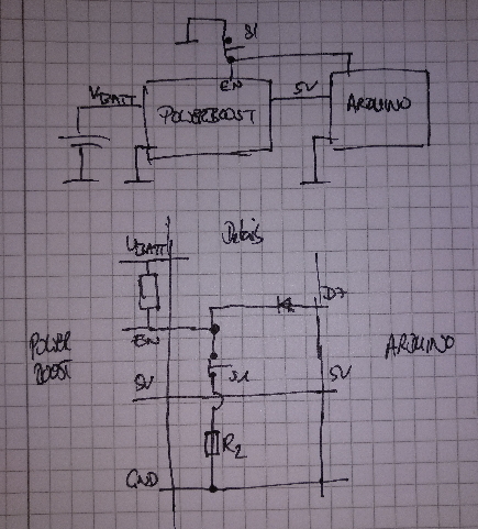
  1. The user presses the button to start the Tonuino. The switch disconnects EN from GND, EN goes to UBATT(HIGH) and 5V to the arduino is enabled. By enabling the arduino, a GPIO is set to high and thus EN is maintained high
  2. To turn off, the arduino sets the GPIO to LOW, thus setting EN to LOW, 5V are disabled and so forth...

My problem: 5V from the Arduino GPIO will always be at 5V and thus higher than the reference voltage of EN (UBATT 3V - 3.7V). I really am afraid that this will damage my lipo. For me this means, I ideally should switch UBATT for EN (safely) and am failing to come up with a solution.

Any pointers are greatly welcome

2
  • The datasheet states that the EN pin can be up to 7V. But you could also, instead of setting the Arduino pin to OUTPUT HIGH, set the Arduino pin to INPUT. The pull-up (R13) on the PowerBoost will then provide Vbat to the EN pin. So it would never see 5V.
    – Gerben
    Commented Jun 16, 2020 at 15:45
  • PS note that as soon and the Boost converter turn off, the power to the Arduino goes off, and the pin will no longer be LOW, turning the boost converter back on. Majenko's solution already fixes that.
    – Gerben
    Commented Jun 16, 2020 at 15:49

1 Answer 1

2

Your biggest problem is that the module defaults to on. There is a 340kΩ resistor pulling the EN pin up to VBAT all the time, so to turn it off you have to actively override that pullup.

Ideally you would modify the module by removing that resistor (R13) and adding your own resistor between the ENABLE and GND pins. You can the override that with both a button and a P-channel FET in parallel to turn the module on.

For example:

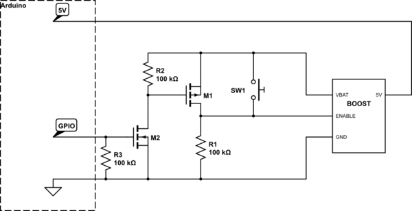
schematic

simulate this circuit – Schematic created using CircuitLab

Now normally R1 pulls ENABLE to ground turning the module off. You press SW1 and it pulls ENABLE up to VBAT and turns it on. 5V then gets supplied to the Arduino, at which point you need to set the GPIO to output and pull it HIGH.

This causes the gate of M2 to be pulled above its threshold voltage (make sure it has a threshold voltage between 0V and 3V) and it starts to conduct pulling the gate of M1 below its threshold voltage (must be between 0V and -2V) bypassing switch SW1 keeping the system enabled.

You can now let go of SW1 and it will all stay powered on until you either set the GPIO LOW or set it to an INPUT.

Note that resetting the Arduino (for programming, for example) would cause the boost module to shut down and require re-powering with SW1 (or through the GPIO if you have the Arduino powered through USB for programming of course).

However if you don't want to or can't modify the module then things get a little nastier.

To make it default to OFF R1 in the above schematic will have to be low enough value that the voltage presented at the ENABLE pin is below 20% of the battery voltage. R1 and the existing 340kΩ pullup resistor form a voltage divider, so you need to calculate the size of resistor that will allow it to be below 20% VBAT.

Since a voltage divider just gives you a proportion of the input voltage whose ratio is the ratio of the "top" resistance in the divider to the total resistance we don't care what the voltage is, only the ratio. And we don't really care about the exact value, only that the result is below 20%. So we can pick a good common value.

However we don't want a value that is too low, because the voltage divider will be draining power from the battery all the time, so the higher the resistances the less the power drain will be.

For example if we pick the common value 47kΩ we see that:

    R2           47000
 ------- = --------------- = 0.11 (11%)
 R1 + R2    340000 + 47000

Which is below the 0.2 (20%) that we want, which is good. Calculating the current at a typical battery voltage of 3.7V we get

     V          3.7
I = --- = -------------- = 0.000010 (10µA)
     R    340000 + 47000

10µA is not much, on the scale of things, but it's good to know about it when you're working from a battery since it will form part of your power budget calculations.

6
  • This is a fantastic answer! Thank you for enlightening me and the time to answer my question. I will see what parts i can get quickly to realize this
    – JoeD
    Commented Jun 16, 2020 at 6:22
  • Hi Majenko, so after a test build on the breadboard, I have to rescind my acceptance of the answer. Here is why: The arduino does turn the powerboost module off - BUT - the gate voltage remains at 2,25V. So a trickle current is running somwhere...
    – JoeD
    Commented Jun 16, 2020 at 21:06
  • Which variant of the circuit are you using? Did you remove R13 or are you trying to work around it?
    – Majenko
    Commented Jun 16, 2020 at 21:08
  • I removed R13 from the circuit
    – JoeD
    Commented Jun 17, 2020 at 4:19
  • There may be some back flow through the Arduino gpio. Isolating it with an n channel MOSFET would cure that. I'll update the schematic shortly.
    – Majenko
    Commented Jun 17, 2020 at 8:03

Your Answer

By clicking “Post Your Answer”, you agree to our terms of service and acknowledge you have read our privacy policy.

Not the answer you're looking for? Browse other questions tagged or ask your own question.