0

My main goal is to use connect the HC-SR04 ultrasonic sensor with ESP8266.

Problem is, HC-SR04 works with 5V while the ESP8266 works with 3.3V In order to solve this, idea would be to use a logical level converter.

I bought some of this 3.3V 5V TTL Bi-directional Logic Level Converter(s) a good while ago, and thought they would fit best for this project.

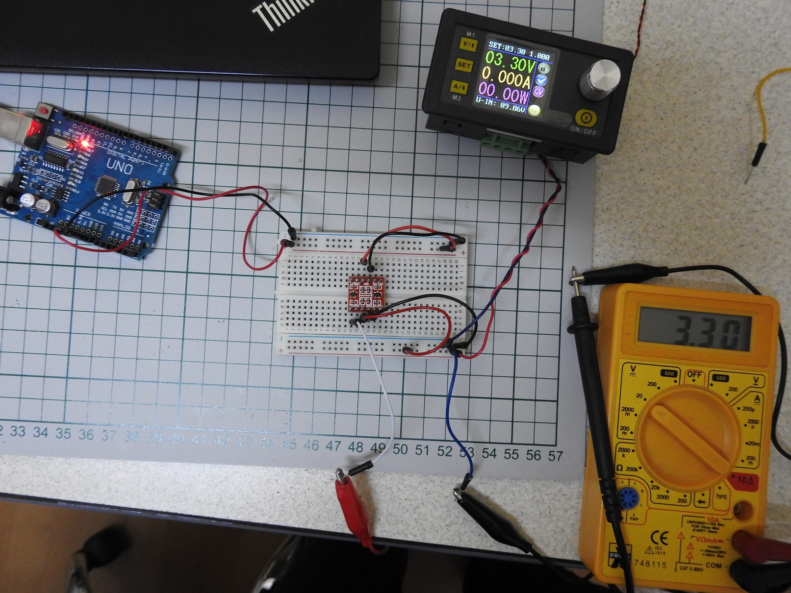
Here's my setup

  • 5V from arduino
  • 3.3V from digital power supply
  • GND connected together
  • Nothing connected to TX0 (HV side)
  • Voltmeter connected to TX1 (LV side), still getting a 3.3V

enter image description here

Here's a closer look at the breadboard connections enter image description here
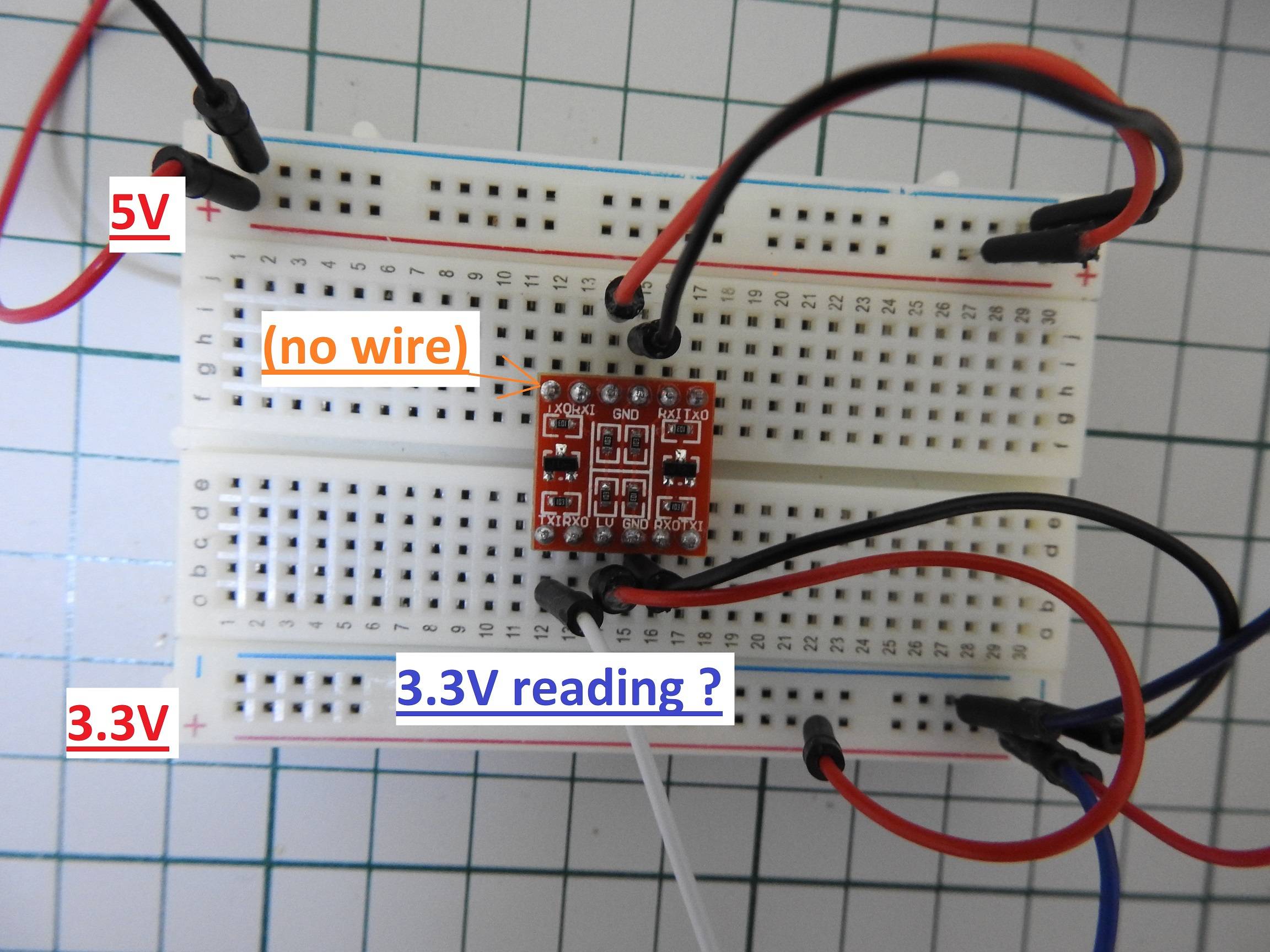
Am I doing something wrong ? Any suggestions would be appreciated !

2
  • 1
    Are you sure you connected it correctly? The description on the seller's site is not clear at all, and at least a bit ambiguous. I'm also not sure if these boards are really bidirectional as the markings seem to indicate Inputs (I) and Outputs (O). What do you see at RXO (Receive-Out?) on the low side if you connect, for example, the RXI (Receive-In?) on the high side to 0V or 5V? It would be very nice if these cheap boards were properly documented...
    – StarCat
    Commented Jan 25, 2020 at 7:48
  • I'm not sure at all. I get 2.5V on RX0 if I connect RXI to 5V, and 0V if I connect RX1 to GND. I agree with the documentation, that's why I was hoping someone here might know more about them Commented Jan 25, 2020 at 11:40

3 Answers 3

1

Edit: Forget the post above if you just want to know how your board is working. Your board is a retired Spurkfun product - clone.

Here you can see the schematics and all info about your board:

https://learn.sparkfun.com/tutorials/retired---using-the-logic-level-converter

Original post:

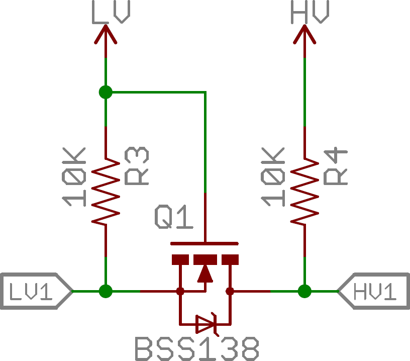
The module you got, use the BSS138 MOSFET. The circuit is easy, and how @Majenko said, it has just 2 pullups: See https://electronics.stackexchange.com/questions/367052/replace-bss138-with-ao3400a-in-level-shifter-circuit

level shifter

But this board is really strange: what means TX0, TX1, RX0, RX1 on the same MOSFET? It is better if you can measure it to be sure how to connect the sensor to the TX.

But there is a better way to solve it: Since you just have 1 input to your ESP, why not use 2 resistors?
5V--- 1k --- 2k --- GND
And connect the ESP input between the 2 resistors? It is even faster, because the MOSFET need up to 20ns to change state.

4
  • Thanks for making some "light". I tried all possible combinations with the module and still can't go from 3.3V -> 5V or the other way around. No wonder it's retired, also name starts with BS.. On the ESP I'll need two pins with the ultrasonic sensor. 1 as input and 1 as output. I'll try what you were saying above with the input pin but how should I go about the output ? Commented Jan 29, 2020 at 18:28
  • The board was made for a serial converter from 5V to 3.3V. This is the reason for RO and RI, or TO and TI. Since in the circuit, the Rx use just 2 resistors, you have to use the T0 and TI. So, put the Esp32 pin to TI, and your sensor input to TO. And invert VL with VH, if you have still 3V, since you want convert from 3V to 5V but the circuit was made to convert 5V to 3.3V. It should not be a problem if you do not use the middle part of this board.
    – Adriano
    Commented Jan 29, 2020 at 20:02
  • I'm a bit worried that if I wire the ESP and sensor with the module and test it like that, it might damage them, if the module doesn't work as expected (eg. draws too much current). Would there be an "easy" way to check 3.3V to 5V, without being the possibility of damaging something ? The 5V to 3.3V works with the resistors Commented Jan 30, 2020 at 10:34
  • Yes, I know what you mean. An easy way to check is to apply a 3.3V to an XI (RI or TI) and see what you get on the output (RI goes to RO and TI goes to TO). How you connected the board is right (GND, LV to 3.3V and HV to 5V), I would just apply a 3.3V to both inputs: RI and TI, and check if you can measure 5V on RO or TO. If you measure still 3.3V, you have to set the 3.3V on RO and TO or invert LV and LH voltages. Just test it without the sensor or Arduino connected on this board.
    – Adriano
    Commented Jan 30, 2020 at 10:46
0

No, you're not doing anything wrong. Those simple MOSFET level shifters work by having both sides pulled up by resistors to their respective power supplies. When one side gets pulled low by a digital signal that LOW is mirrored to the other side of the MOSFET.

If you connect your TX0 pin to GND you will see the TX1 pin go to 0V.

2
  • Tried it, but it's not working. Also the current on the digital power supply increased to 0.7A - i.imgur.com/UG5dj6R.png Commented Jan 24, 2020 at 23:27
  • It might be only a one-way then. I notice on closer inspection that it's not TX0 and TX1 bit TXI and TXO. That's Input and Output. For 5V->3.3v you should use RXI and RXO for 5V (I) and 3.3V (O), which just uses a simple voltage divider.
    – Majenko
    Commented Jan 25, 2020 at 12:51
0

Check this out: https://learn.sparkfun.com/tutorials/bi-directional-logic-level-converter-hookup-guide/all This article gives a comprehensive explanation about the bi-directional logic level converter and it's connection in a circuit.

Your Answer

By clicking “Post Your Answer”, you agree to our terms of service and acknowledge you have read our privacy policy.

Not the answer you're looking for? Browse other questions tagged or ask your own question.