1

I don't know if this question belong here or on electronics SE.

A manufacturer just sent me a personalize device which include an ESP-32 and a Water Sensor.

My problem is that I don't know how to retrieve the water sensor data (if there is water or not).
When I used my Arduino Nano and a Funduino Water Sensor, it was easy to retrieve the value because this sensor got 3 connectors (VCC, GND, Data), I just had to do a basic analogRead(DATA_PIN).

But now, as you can see on the diagram bellow, the water sensor is just composed of 2 wires. I presume that it will detect water when these two wires are going to be connected by water.

So, How to detect the presence of water in Arduino using only these 2 wires ?

What I tried :

  • Analog Read on the pin GPIO33
  • Digital Read on the pin GPIO33
  • Try to use TOUCH_PAD with this pin using touchAttachInterrupt(T8, callback, Threshold); but callback was never called
  • Contact the manufacturer (He said that it works perfectly, he used touch_pad for testing but never used Arduino IDE, only ESP-IDF that I really don't know)
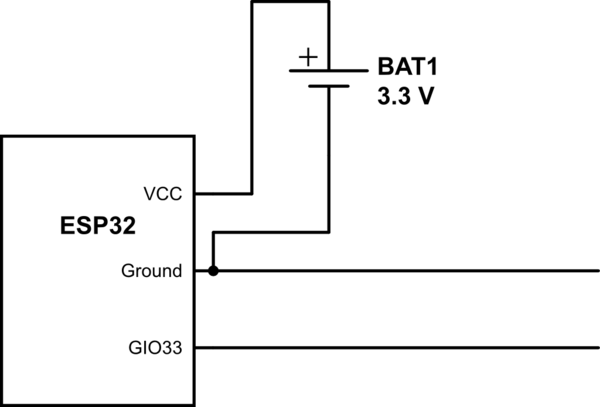
schematic

simulate this circuit – Schematic created using CircuitLab

EDIT:

This image represent the back of the device with the sensor, inner wire is directly connected to GND and outer wire is connected to GPIO_33. This is all, there is not hidden connectors or something else.

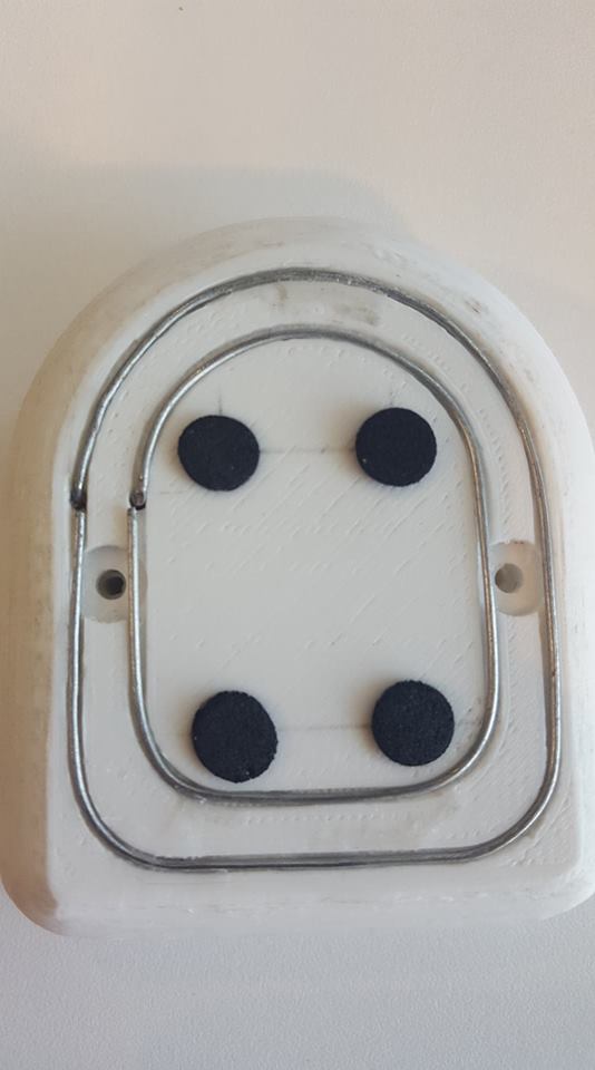
Back of the device with these 2 wires

4
  • You'll have to show us what this mystery sensor is.
    – Majenko
    Commented Jul 31, 2018 at 15:48
  • @Majenko I edited the question with a photo of the device
    – Gazouu
    Commented Jul 31, 2018 at 15:58
  • So it is just literally 2 bare wires then? Nothing else?
    – Majenko
    Commented Jul 31, 2018 at 15:59
  • Yep that's it, one connected to GPIO_33 and the other connected to GROUND
    – Gazouu
    Commented Jul 31, 2018 at 16:00

1 Answer 1

5

Since all you have is 2 bare wires, the water simply forms a resistor between them.

You can use it as part of a resistive divider, with a fixed resistor between your analog input and +3.3V. The resistance between the wires will change from infinite (dry) to something much lower (wet) and the reading you get from the ADC will depict that.

You will need to experiment with different resistances in order to get reasonable values, but start with 10kΩ, or 100kΩ. If you use a very high resistance (in the order of 1MΩ or more) you may even be able to use it like a simple switch and connect it to a digital input.

Be warned, though, that this method will cause a small amount of electrolysis, causing one electrode to be eroded away and the other to gain extra material. For this reason it can be good to connect the resistor to a GPIO pin instead of directly to +3.3V and switch the GPIO pin HIGH when you want to do a reading (to provide power) and LOW (or INPUT) when at other times (to remove power). This will greatly increase the lifetime of your water sensor.

2
  • Hum, the device is already functional, and I don't have to add electronic parts (according to the manufacturer). I just need a way to obtain the value I guess
    – Gazouu
    Commented Jul 31, 2018 at 16:07
  • 3
    I am not familiar with the ESP32, but you may be able to do it by turning on an internal pullup resistor on the GPIO pin.
    – Majenko
    Commented Jul 31, 2018 at 16:23

Your Answer

By clicking “Post Your Answer”, you agree to our terms of service and acknowledge you have read our privacy policy.

Not the answer you're looking for? Browse other questions tagged or ask your own question.