0

I'm trying to program an ESP8266 ESP-01 module to let it connect to my personal wifi network and activate a wireless relay that I've bought.

No problems with Wifi connection so I've omitted the code about it, my problem is to find what is the right PIN to set to LOW/HIGH to control my relay. Setting relayPin to 1 as shown in this code works and with it I can see the embedded LED turning on and off.

const int relayPin = 1;

void setup() {
    pinMode(relayPin, OUTPUT);
}

void loop() {
    Serial.println("Close Relay for 100 ms and then Open");
    digitalWrite(relayPin, LOW);
    delay(100);
    digitalWrite(relayPin, HIGH);
    delay(200);
}

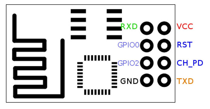
Surfing the web I've found the following diagram about the ESP8266 ESP-01 module:

ESP8266 ESP-01 module

I've tried to set relayPin to 0 or to 2 but the relay doesn't activate/deactivate.

So, what is the right PIN number to set in my relayPin constant to control the GPIO0 port?

The relay works succesfully if I give him +3.3V on GPIO0 with an external power.

Thanks in advance

5
  • 2
    why don't you just write test code that tries all the pins in sequence?
    – jsotola
    Commented Apr 28, 2018 at 1:07
  • @jsotola tried with pastebin.com/pNsZY1ZX but nothing happens :( Commented Apr 28, 2018 at 12:24
  • check the traces on the relay PCB
    – Juraj
    Commented Apr 28, 2018 at 12:32
  • @Juraj how can I do that? Commented Apr 28, 2018 at 14:34
  • I'm in the same boat as Roberto and wondering if this issue was resolved and what was the solution. Also interested in the firmware that was used in the ESP.
    – naji
    Commented Aug 22, 2019 at 5:23

5 Answers 5

2

most GPIO pins on the ESP8266 "boot" up in INPUT mode

You'll need to

const int relayPin = 0; // or 2

void setup() 
{
    pinMode(relayPin, OUTPUT);
}

The reason GPIO1 works is because GPIO1 is serial TxD - so, it's set to output

1
  • Thanks for your comment! It was already written in my code but I've forgotten to write it, now I've edited the 1st post ;) Thanks Commented Apr 28, 2018 at 10:39
1

Looking at better pictures of the PCB on ALIExpress it looks like GPIO0 is used to switch the relay.

What that pin maps to, though, depends on what board you have selected in the IDE.

5
  • Thanks for your answer Majenko! In Arduino IDE I've set "Generic ESP8266 Module", but where can I find the PIN mapping? :) Commented Apr 27, 2018 at 22:32
  • "PIN mapping"? GPIO0 is pin 0 ... GPIO1 is pin 1 ... up to GPIO16 is pin 16 ... it's not hard :p Commented Apr 28, 2018 at 10:49
  • @JaromandaX In this case it looks like yes, it's a 1:1 mapping between the GPIO number and the Arduino pin number (which is default). However, since digitalWrite() is a weak alias to __digitalWrite() it's perfectly possible that a board definition overrides that function with its own to implement a different numbering scheme.
    – Majenko
    Commented Apr 28, 2018 at 10:54
  • Pin 1 is gpio 1 always on every 8266. Some boards may have d0 d1 etc. But that is completely irrelevant to an esp01 Commented Apr 28, 2018 at 11:44
  • Ok thanks, I've tried to set relayPin to 0 but nothing happens on the relay :( I've also tried with this sketch but nothing happens: pastebin.com/pNsZY1ZX What is missing? Commented Apr 28, 2018 at 12:23
0

1 solution I did is to use rx [GPIO 3] to drive relay. For this,

  1. Need to short the GPIO 0 and GPIO 3(Rx) pin on the relay board.
  2. While inserting the ESP-01, either bend the GPIO 0 or completely remove it from ESP-01 board. Be careful, on removing you wil find difficult to program the ESP-01 module again because GPIO 0 should go low at boot time to enable program mode. And this is the reason why GPIO 0 is HIGH on boot.

If you want, you can try this product Smart Switch. Android Based ESP01 Relay Module

0

I had this exact same problem. Solution was to put 5 volts on the relay. There is a regulator on the wireless relay that gives 3v to the ESP-01 and not 5v. But 5v is required for the relay to work.

-1

You can use any pin of the esp-01 You may want to tell the TX and Rx pins though to behave like regular I/O with the pinMode/Function_3 command as described here:

https://arduinodiy.wordpress.com/2018/06/14/simple-wifi-relay-board-or-diy-sonoff-sv-sonoff-4-channel-2/

1
  • 1
    the question is about a pcb with relay already wired to a pin
    – Juraj
    Commented Nov 21, 2018 at 8:43

Not the answer you're looking for? Browse other questions tagged or ask your own question.