1

I am trying to learn how to make a shift register work. I have been working off of the Arduino ShiftOut tutorial.

My issue is that the shift register isn't working when the circuit is powered and I am not sure what is wrong. I suspect the issue is with pins 10-13 on the 74HC595?

I have done this with an actual board and the 123d.circuits.io simulator with the same result:

http://123d.circuits.io/circuits/444111-shift-register
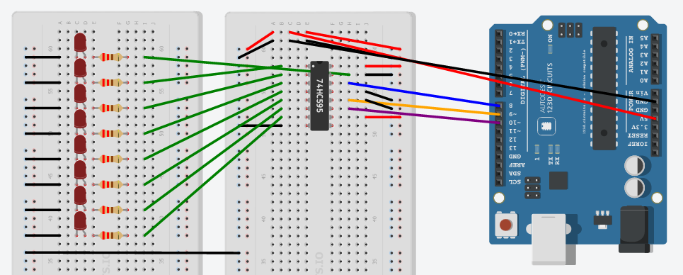
enter image description here

The code is very simple and taken from the tutorial:

// SH_CP; 11
const int clockPin = 9;
// DS; 15
const int dataPin = 8;
// ST_CP; 12
const int latchPin = 10;

void setup() {
  pinMode(clockPin, OUTPUT);
  pinMode(dataPin, OUTPUT);
  pinMode(latchPin, OUTPUT);

  Serial.begin(9600);
  Serial.println("reset");
}

void loop() {
  for (int number = 0; number < 256; number++) {
    Serial.println(number);
    digitalWrite(latchPin, LOW);
    shiftOut(dataPin, clockPin, MSBFIRST, number);
    digitalWrite(latchPin, HIGH);
    delay(500);
  }
}
2
  • 1
    Why is GND (also) connected to Q0? Idem for STCP? You also need to swap the wires going to pins 11 and 12 on the chip.
    – Gerben
    Commented Nov 18, 2014 at 19:23
  • @Gerben good catch that was a mistake. see answer below for the other half of the fix Commented Nov 18, 2014 at 19:47

1 Answer 1

2

Solution: Remove ground from Q0 as Gerben correctly pointed out in comments.

Also: rotate LEDs 90 degrees so that the anode and cathode are on different rows.

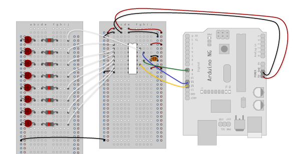
What was tripping me up is in the Arduino tutorial diagram is a little unclear on this (I now understand why their way is correct and my way (in the question) was wrong:

enter image description here

2

Your Answer

By clicking “Post Your Answer”, you agree to our terms of service and acknowledge you have read our privacy policy.

Not the answer you're looking for? Browse other questions tagged or ask your own question.