1

I am using Arduino UNO together with a SPI ADC (LTC1859) and SRAM (23CL1024) to record a series of data points at approx 2 kHz sampling rate (let's say a few thousand data points).

I have some questions about how to ensure the data points are sampled at uniform time intervals, down to the precision of a clock cycle.

What are the limitations of Arduino macros in respect to this? Can I replace SPI.transfer() with some lower-level code that will make an improvement?

Even if my code is precise, is the relatively low CPU speed of 16 MHz something to worry about for data sampling rates up to a few kHz?

The time-critical part of my code is as follows, and I'd appreciate suggestions:

**RE-EDIT. As has been requested, the ADC is LTC1859 and triggers on the slave select falling edge active high of input on the CONVST pin, which is the same time that I make ADC SS low (first line inside the for loop).

Digital outputs:
CONVST = Port B, bit 2
SS ADC = Port B, bit 1
SS SRAM = Port B, bit 0

      for(unsigned int i=0;i<DATA_LENGTH;i++){
        PORTB=B11000101;                     // ADC Slave select
        __builtin_avr_delay_cycles(112);     // ADC conversion time
        DATA_MSB=SPI.transfer(ADCbyte1);     // Get 16-bit ADC value as 2 bytes
        DATA_LSB=SPI.transfer(ADCbyte2);
        PORTB=B11000010;                     // SRAM Slave select
        SPI.transfer(WRITE);                 // Write data value to SRAM as 2 bytes
        SPI.transfer((uint8_t)(DATA_ADDRESS >> 16)&0xFF);
        SPI.transfer((uint8_t)(DATA_ADDRESS >> 8)&0xFF);
        SPI.transfer((uint8_t)(DATA_ADDRESS));
        SPI.transfer(DATA_MSB);
        SPI.transfer(DATA_LSB);
        PORTB=B11000011;                     // Deselect both ADC and SRAM slaves
        DATA_ADDRESS++;
        DATA_ADDRESS++; 
        __builtin_avr_delay_cycles(7600);    // Delay makes 1/sampling rate.  7600 = 2 kHz
      }                                      // Repeat for number of data points

**EDIT. Also, I have done some further tests and replaced occurrences of SPI.transfer(data); with SPDR = data; followed by waiting a constant number of clock cycles to ensure the data clears. I checked out the timing accuracy by measuring a sine wave voltage input and analyzing the FFT of the recorded data. Overall timing accuracy was improved but I do not see evidence that this part of code limits how uniformly the data are sampled. I have not tried Nick Gammon's suggestion yet to use timer interrupts.

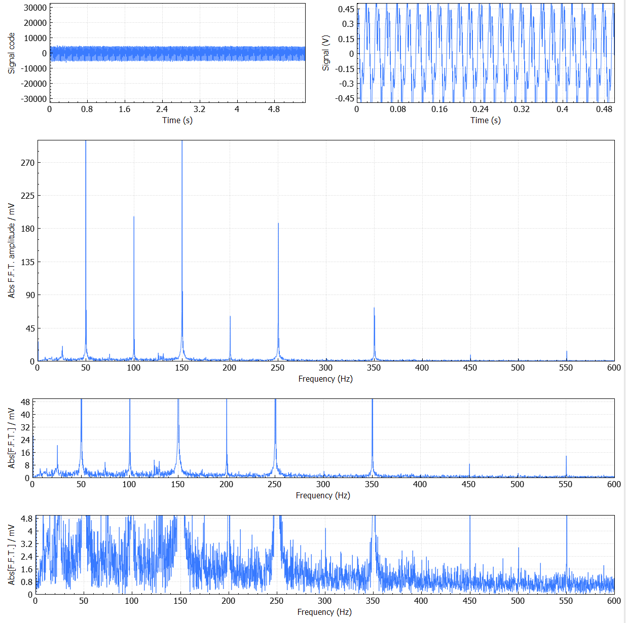
Below is an example of the real-world data that I am recording. The ADC is digitizing data at 16 bit, 2 KHz from a magnetometer with around 10-15 T/Hz1/2 sensitivity, then passing to a PC running Qt where I plot the time-domain data and frequency-domain data after FFT.

The signal is laboratory magnetic background and contains harmonics of the 50 Hz line frequency from mains cables etc. The point of showing the data is that I am not stuck getting the data acquisition to work. I want to improve the data acquisition code as far as possible within the limits of Arduino.

Data that I have measured

SOLUTION: I modified Edgar Bonet's code in the accepted answer to use timer1 for PWM control of ADC trigger (CONVST, OC1B = Arduino pin 10). This worked successfully.

Learning points for me were:

(1) much greater accuracy in ADC sampling rate. The resonator frequency is accurate enough for my purposes at kHz sampling that I don't need fiddly calibrations of for loop duration;

(2) much better way of programming a DAQ. Using the state machine concept, I can run other processes in parallel with the DAQ without penalties in timing accuracy.

void loop(){

switch (statemachine){

// other cases, including reading serial data from PC

case 2: // Initialize data acquisition
cli();
data_address=0;
data_counter=0;
statemachine=3;
TCCR1A=0;
TCCR1B=0;
OCR1A=124; // 16 MHz / (64 * 125) = 2000 Hz
OCR1B=1;
TCCR1A = _BV(COM1B1)  // Clear pin OC1B on compare match, set at BOTTOM, noninverting
| _BV(WGM10)          // fast PWM mode 15, TOP = OCR1A
| _BV(WGM11) ;        // fast PWM mode 15.
TCCR1B = _BV(WGM12)   // fast PWM mode 15
| _BV(WGM13)          // fast PWM mode 15
| _BV(CS11)           // Set timer prescaler to 64.
| _BV(CS10) ;         // Set timer prescaler to 64.
TCNT1=0x03;
TIFR1 |= _BV(OCF1A); // Clear match flag  
break;

case 3: // Acquire data and store.
loop_until_bit_is_set(TIFR1,OCF1A);
TIFR1 |= _BV(OCF1A);              // Clear match flag
PORTB=B11000101;                  // ADC SS
__builtin_avr_delay_cycles(160);  // 10 us 
msb=SPI.transfer(ADCbyte1);
lsb=SPI.transfer(ADCbyte2);
PORTB=B11000010;                  // SRAM SS
SPI.transfer(WRITE);
SPI.transfer((uint8_t)(data_address >> 16) & 0xFF);
SPI.transfer((uint8_t)(data_address >> 8)  & 0xFF);
SPI.transfer((uint8_t)(data_address));
SPI.transfer(msb);
SPI.transfer(lsb); 
PORTB=B11000011;
data_address++;
data_address++; 
data_counter++;
if(data_counter==data_length){statemachine=4;} // Data capture complete
break;

// other cases, including data transfer to PC
}
}
10
  • 2
    You should consider triggering the most time-critical part of your code using a hardware timer rather than delay loops. Commented Feb 20, 2018 at 21:37
  • You think the for() loop is the most likely source of error? I have considered hardware timing but thought that each SPI.transfer() waits for an interrupt to conclude the transaction. If I did do hardware timing, what timer of the AVR is best to use? Note that I care most about uniform timing and not absolute accuracy.
    – MichaelT
    Commented Feb 20, 2018 at 21:51
  • 1
    First thing you need to do is look at the chip data sheet and see exactly what triggers a conversion. Is it a particular part of the SPI cycle, like a given clock or deassertion of the select? Is there an option to use a distinct signal to trigger it after priming it with the SPI? Or is this one of the ADCs where the a successive-approximation conversion is directly clocked by the SPI, and any jitter in the SPI clock contaminates your measurement? If you do keep software in the critical loop, you'll want to disable the interrupt that advances the Arduino millis() Commented Feb 20, 2018 at 21:59
  • 1
    Again, you need to read the data sheet and determine what actually governs the timing of the ADC. It's not a question of speed but of which specific action (or actions) causes the ADC to take a reading. Whatever that is, it is what you need to remove jitter from. Commented Feb 21, 2018 at 6:48
  • 1
    @Gerben - measuring across a lot of samples averages the timing - that's important for things like buffer usage, but it doesn't reveal if there is jitter to the samples or the clock which may be used to measure them. Commented Feb 21, 2018 at 19:18

2 Answers 2

2

the ADC is LTC1859 and triggers on the slave select falling edge.

No, it doesn't. Here is a link to its datasheet. It has a pin labeled CONVST, for “conversion start”. According to the section Pin functions, “This active high signal starts a conversion on its rising edge.”

If you want your sampling to be at 2 kHz with cycle-accurate timings, you have to send to this pin a train of pulses which are at least 40 ns wide and have a period of 500 µs, i.e. 8,000 CPU cycles. This can be done with any of the three timers of the Uno. For example, you can set Timer 2 to repeatedly count from 0 to 124 with a prescaler of 64. Your initialization would have something like this:

// Initial transfer to configure the ADC.
PORTB &= ~_BV(SS_ADC);
SPI.transfer(ADCbyte1);
SPI.transfer(ADCbyte2);
PORTB |= _BV(SS_ADC);

// Configure Timer 2 for PWM on pin OC2B = PD3 = digital 3.
DDRD  |= _BV(PD3);    // pin PD3 as output
TCCR2A = 0;           // undo the Arduino core's configuration
TCCR2B = 0;           // ditto
OCR2A  = 125 - 1;     // period = 64 * 125 CPU cycles = 500 us
OCR2B  =   2 - 1;     // high for 64 *   2 CPU cycles =   8 us
TCNT2  = 122;         // first pulse in 8 to 12 us
TIFR2 |= _BV(OCF2B);  // clear the output compare flag
TCCR2A = _BV(COM2B1)  // non-inverting PWM on pin OC2B
       | _BV(WGM20)   // mode 7: fast PWM, TOP = OCR2A
       | _BV(WGM21);  // ditto
TCCR2B = _BV(WGM22)   // ditto
       | _BV(CS22);   // clock at F_CPU/64

Note that the timer will also set a flag when the pulse is done, at which time you can start the data transfer. You would then start your data-taking loop with:

// Wait for the output compare flag.
loop_until_bit_is_set(TIFR2, OCF2B);

// Clear the flag.
TIFR2 |= _BV(OCF2B);

// Now transfer the data.
...

Edit 1: I would just want to add that cycle accurate timing does not mean perfectly uniform timing. The Arduino Uno is clocked off a ceramic resonator. This kind of resonator, in addition to having bad accuracy, has poor frequency stability. To get an idea of how bad it can be, see the Allan deviation plots on the article Arduino clock frequency accuracy, by Joris van Rantwijk.

Edit 2: After some tests, I wrote a more complete initialization:

  • An initial SPI transaction is used to prime the ADC, as suggested by Chris Stratton
  • the PWM pin is configured as an output
  • the Arduino core's Timer setup is undone before applying the new configuration
  • the very first pulse on CONVST is scheduled to happen not too long after the initialization, yet after tACQ
  • the output compare flag is cleared during the initialization.
5
  • Yes, though to clarify, the conversion must be primed by an SPI operation, then the actual measurement triggered by CONVST. Typically the way to get regular spacing is to have software prime early, and then as wisely shown here have a hardware timer trigger the actual conversion at more evenly spaced intervals than software will normally achieve. Then software claims the data and prime for the next. Commented Feb 21, 2018 at 19:36
  • You are right, and that was sloppy of me. The conversion is triggered by CONVST which happens to be the same time that I slave-select the ADC. Thanks for the info on hardware timer interrupt, I'll investigate that.
    – MichaelT
    Commented Feb 22, 2018 at 12:02
  • @MichaelT: I think you misread my answer. I am not suggesting you use a timer interrupt, I am suggesting you use a timer to generate a low-jitter trigger signal for your ADC. Then you can use an interrupt flag (namely OCF2B) to know when it is safe to do the data transfer. Note that the interrupt flag is independent from the actual interrupt mechanism: it can be used when the interrupt is disabled, which is the case here. I am suggesting a polling, rather than interrupt based, approach. Of course, you can do interrupts if you prefer, but you don't have to. Commented Feb 22, 2018 at 14:20
  • OK, got it. I will try that approach and append the findings to my original posted question. I think it will be interesting to compare with the code I have been using so far and see if there is much difference.
    – MichaelT
    Commented Feb 22, 2018 at 20:28
  • Thanks, in the end I used timer1 not timer2. While I don't need the 16-bit timer resolution, timer1 controls PWM on Arduino pin 10 and that saves me making a new circuit board/"shield" for the ADC, for the time being. I'll post the code in the main question
    – MichaelT
    Commented Mar 13, 2018 at 12:21
1

I did a project generating VGA signals that required highly precise timing for the sync pulses.

The technique that worked for me was:

  • Use the hardware timers to generate the required pulse interval
  • Put the processor to sleep (set_sleep_mode (SLEEP_MODE_IDLE);) to remove jitter caused by whether the interrupt occurred while an instruction was executing (interrupts can't interrupt half-way through a multi-cycle instruction).

So in your case I would set up the timer (eg. Timer 1) to generate the appropriate interrupts. Then go to sleep waiting for the interrupt. The ISR doesn't have to do anything in particular, you just want to pause until the interrupt happens. For example you could do this:

EMPTY_INTERRUPT (TIMER1_COMPA_vect);

That will generate a "do nothing" interrupt handler for Timer 1 compare-A vector.

Once the interrupt happens you will pass the sleep instruction and then you can do your ADC sample and send the results. You may want to scale back the ADC clock a bit (eg. a prescaler of 64) to speed up the ADC sample a bit.

See my page about the ADC and my page about interrupts.


Automatic mode

Another possibility is to use the automatic ADC conversion, as in this example from my page about the ADC:

const byte adcPin = 0;  // A0

const int MAX_RESULTS = 256;

volatile int results [MAX_RESULTS];
volatile int resultNumber;

// ADC complete ISR
ISR (ADC_vect)
  {
  if (resultNumber >= MAX_RESULTS)
    ADCSRA = 0;  // turn off ADC
  else
    results [resultNumber++] = ADC;
  }  // end of ADC_vect

EMPTY_INTERRUPT (TIMER1_COMPB_vect);

void setup ()
  {
  Serial.begin (115200);
  Serial.println ();

  // reset Timer 1
  TCCR1A = 0;
  TCCR1B = 0;
  TCNT1 = 0;
  TCCR1B = bit (CS11) | bit (WGM12);  // CTC, prescaler of 8
  TIMSK1 = bit (OCIE1B);  // WTF?
  OCR1A = 39;    
  OCR1B = 39;   // 20 uS - sampling frequency 50 kHz

  ADCSRA =  bit (ADEN) | bit (ADIE) | bit (ADIF);   // turn ADC on, want interrupt on completion
  ADCSRA |= bit (ADPS2);  // Prescaler of 16
  ADMUX = bit (REFS0) | (adcPin & 7);
  ADCSRB = bit (ADTS0) | bit (ADTS2);  // Timer/Counter1 Compare Match B
  ADCSRA |= bit (ADATE);   // turn on automatic triggering

  // wait for buffer to fill
  while (resultNumber < MAX_RESULTS)
    { }

  for (int i = 0; i < MAX_RESULTS; i++)
    Serial.println (results [i]);

  }  // end of setup

void loop () { }

The code above will take 256 samples at 50 kHz frequency. You could modify the ISR to send the results by SPI (SPI transfers should be OK inside an ISR) if you needed to take more samples and save them elsewhere.


Even if my code is precise, is the relatively low CPU speed of 16 MHz something to worry about for data sampling rates up to a few kHz?

No, I don't think so.

Your Answer

By clicking “Post Your Answer”, you agree to our terms of service and acknowledge you have read our privacy policy.

Not the answer you're looking for? Browse other questions tagged or ask your own question.