3

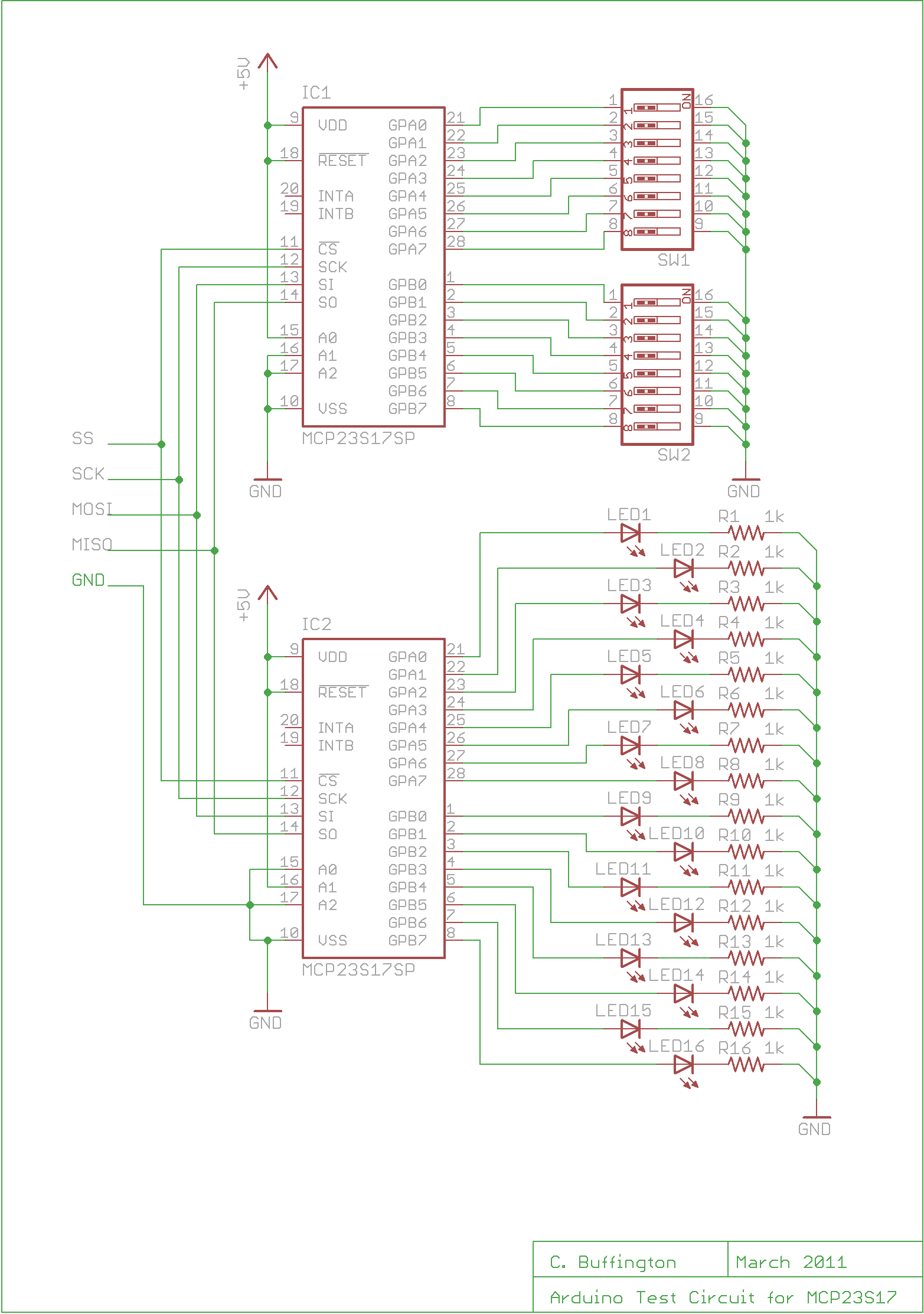
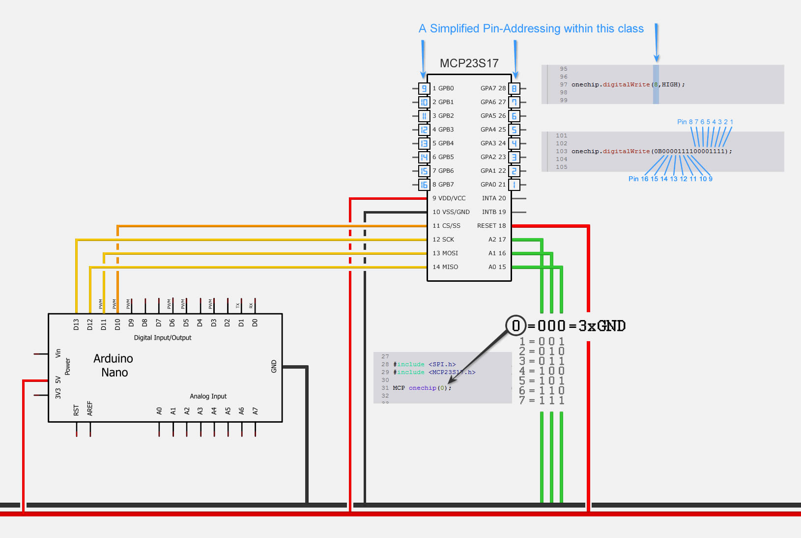
I would like to use 7 MCP23S17 as output expanders on one SPI bus. Every IC has its own address from 0 to 6. The first MCP23S17 can be written with no problem. The second chip did not work properly. The CS pin of the MCP23S17 is set like at the all other 4 ICs.

Does anybody have experience with more then 4 MCP23S17 on SPI? Could anyone help?

#include <SPI.h>
#include <MCP23S17.h>

MCP A(0, 10);
MCP B(1, 8);
int d = 250;

void setup() {
  A.begin();
  B.begin();
  for (int k = 1; k <= 16; k++) {
    A.pinMode(k, OUTPUT);
    B.pinMode(k, OUTPUT);
  }
}

void loop() {
  //////////// ON THE LIGHT ONE BY ONE  FROM BEGGING
  for (int f = 1; f <= 16; f++) {
    A.digitalWrite(f, HIGH);
    delay(d );
  }
  for (int f = 1; f <= 16; f++) {
    B.digitalWrite(f, HIGH);
    delay(d );
  }
  ////////////  OFF THE LIGHT ONE BY ONE  FROM BEGINNIG
  for (int f = 1; f <= 16; f++) {
    A.digitalWrite(f, LOW);
    delay(d);
  }
  for (int f = 1; f <= 16; f++) {
    B.digitalWrite(f, LOW);
    delay(d);
  }
}

enter image description here

enter image description here

7
  • Perhaps you have a wiring, logic, or programming error in your address decoding. Please edit your question to include a Minimal, Complete, and Verifiable example of code and a circuit diagram. Commented Jun 28, 2017 at 13:46
  • view now sir my question Commented Jun 28, 2017 at 14:10
  • 1
    Which library are you using?
    – Majenko
    Commented Jun 28, 2017 at 15:52
  • 1
    Also do you know how the address pins work?
    – Majenko
    Commented Jun 28, 2017 at 15:52
  • 1
    The diagram shows only one SS pin going to both chips. Is that intentional? If that's the case, then you only need to send things out once since all the chips will receive the same thing.
    – Delta_G
    Commented Sep 29, 2017 at 22:29

2 Answers 2

2
 MCP A(0, 9);                              
 MCP B(1, 8);
 MCP C(2, 7);                              
 MCP D(3, 6);
 MCP E(4, 5);                              
 MCP F(5, 3);
  • CS on pin 10 is often used for Ethernet
  • CS on pin 4 is often used for SD
2
  • How is this supposed to solve the problem? As I can see, he is not using an Ethernet or an SD shield.
    – gre_gor
    Commented Jun 28, 2017 at 16:49
  • Hi gre_gor, adress and chipselect 6 time different...
    – rainer
    Commented Jul 19, 2017 at 18:08
1

Assuming that the adressing is correct and all the modules work fine individually, there are some things you can do:

  • try to disable the slave select of the modules that aren’t require to communicate at a certain time, there are examples for that

  • add a bit of code where you define chip select as an input for all but one and see if you can communicate with that one. Do that for all of them

  • remove MISO pin from all but one and see if you can communicate with that one. Do that for all of them

  • use a tri-state buffer through which you connect the MISO pin and use chip select for enabling the buffer. This buffer puts the MISO pin into a state of high impedance when a certain module is not used for communication and prevents fata from being lost

Your Answer

By clicking “Post Your Answer”, you agree to our terms of service and acknowledge you have read our privacy policy.

Not the answer you're looking for? Browse other questions tagged or ask your own question.