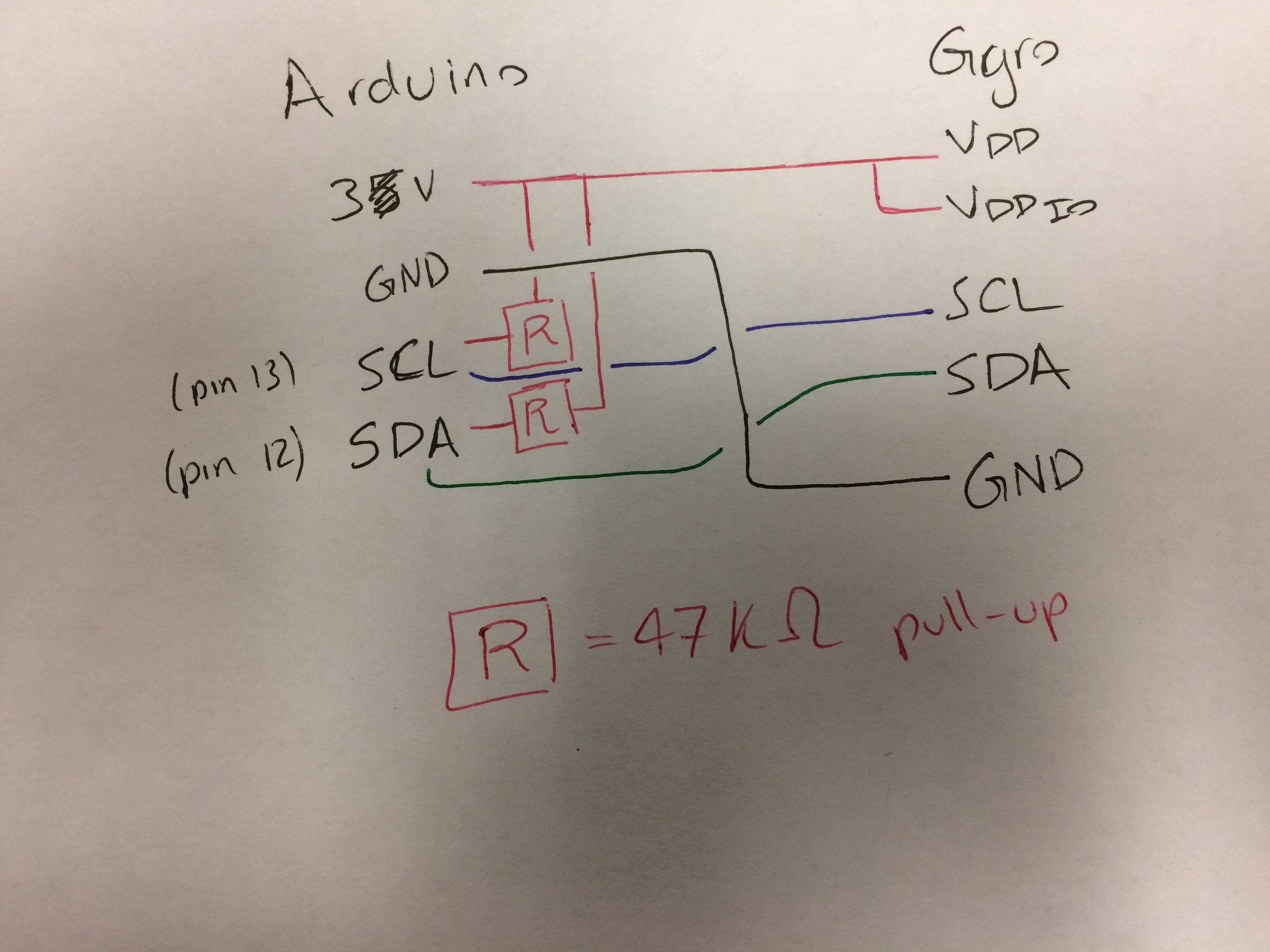
parts
- Three-axis rate gyro on breakout board: gyro datasheet, breakout board "datasheet"
- Arduino Uno: pinout
goal: I want to periodically read a single axes' angular rate. As rvbarreto pointed out, Adafruit built an Arduino library for this sensor, so I'm playing around with its example file.
I have a 5600 Ohm pull-up connected to the SDA and SCL pins each on the Arduino. The internal pull-ups of the Arduino are too weak according to this thread.
code: (Adafruit library's sensorapi example)
#include <Wire.h>
#include <Adafruit_Sensor.h>
#include <Adafruit_FXAS21002C.h>

/* Assign a unique ID to this sensor at the same time */
Adafruit_FXAS21002C gyro = Adafruit_FXAS21002C(0x0021002C);
//Adafruit_FXAS21002C gyro = Adafruit_FXAS21002C(0x21);

void displaySensorDetails(void)
{
  sensor_t sensor;
  gyro.getSensor(&sensor);
  Serial.println("------------------------------------");
  Serial.print  ("Sensor:       "); Serial.println(sensor.name);
  Serial.print  ("Driver Ver:   "); Serial.println(sensor.version);
  Serial.print  ("Unique ID:    0x"); Serial.println(sensor.sensor_id, HEX);
  Serial.print  ("Max Value:    "); Serial.print(sensor.max_value); Serial.println(" rad/s");
  Serial.print  ("Min Value:    "); Serial.print(sensor.min_value); Serial.println(" rad/s");
  Serial.print  ("Resolution:   "); Serial.print(sensor.resolution); Serial.println(" rad/s");
  Serial.println("------------------------------------");
  Serial.println("");
  delay(500);
}

void setup(void)
{
  Serial.begin(9600);

  /* Wait for the Serial Monitor */
  while (!Serial) {
    delay(1);
  }

  Serial.println("Gyroscope Test"); Serial.println("");

  /* Initialise the sensor */
  if(!gyro.begin())
  {
    /* There was a problem detecting the FXAS21002C ... check your connections */
    Serial.println("Ooops, no FXAS21002C detected ... Check your wiring!");
    while(1);
  }

  /* Display some basic information on this sensor */
  displaySensorDetails();
}

void loop(void)
{
  /* Get a new sensor event */
  sensors_event_t event;
  gyro.getEvent(&event);

  /* Display the results (speed is measured in rad/s) */
  Serial.print("X: "); Serial.print(event.gyro.x); Serial.print("  ");
  Serial.print("Y: "); Serial.print(event.gyro.y); Serial.print("  ");
  Serial.print("Z: "); Serial.print(event.gyro.z); Serial.print("  ");
  Serial.println("rad/s ");
  delay(500);
}
NOTE: I noticed that Adafruit's Github had removed a line of code (line 67) in their library's main .cpp file. I edited my library code to reflect that change.
problem: I keep getting the "Ooops, no FXAS21002C detected ... Check your wiring!" error message.
questions:
- Am I connecting my pull-up resistors correctly?
- Should I not power VDD and VDD_IO on the same rail? Can they even be powered by the Uno?


Sketch > Include Library > Manage Libraryand then type "FXAS21002C" and you will see it. Just install it and you will have the library and examples to test, explore and get this working.