4

I'm working on creating a circuit where I'm trying to have the ability to switch multiple strands of LED rope on and off at a time using an Arduino and a multiplexer.

With my current configuration, I have the a circuit and a sketch that will cycle through the various LED rope strands, turning them on and off.

What I'm not sure how to do is modify my sketch / circuit so that I can turn ALL of the rope strands on and off, as well as individually.

Below is my current Arduino sketch:

//Mux control pins
int s0 = 8;
int s1 = 9;
int s2 = 10;
int s3 = 11;

//Mux in "SIG" pin
int SIG_pin = 3;

int testValue = 255;


void setup(){
  pinMode(s0, OUTPUT); 
  pinMode(s1, OUTPUT); 
  pinMode(s2, OUTPUT); 
  pinMode(s3, OUTPUT); 


  pinMode(SIG_pin, OUTPUT);

  digitalWrite(s0, LOW);
  digitalWrite(s1, LOW);
  digitalWrite(s2, LOW);
  digitalWrite(s3, LOW);

}


void loop(){

  //Loop through and read all 16 values
  //Reports back Value at channel 6 is: 346
  for(int i = 0; i < 9 ; i ++){
    delay(1000);
    writeMux(i);    
  }
}


int writeMux(int channel){
  int controlPin[] = {s0, s1, s2, s3};

  int muxChannel[10][4]={
    {0,0,0,0}, //channel 0
    {1,0,0,0}, //channel 1
    {0,1,0,0}, //channel 2
    {1,1,0,0}, //channel 3
    {0,0,1,0}, //channel 4
    {1,0,1,0}, //channel 5
    {0,1,1,0}, //channel 6
    {1,1,1,0}, //channel 7
    {0,0,0,1}, //channel 8
    {1,0,0,1}, //channel 9
    {0,1,0,1}, //channel 10
    {1,1,0,1}, //channel 11
    {0,0,1,1}, //channel 12
    {1,0,1,1}, //channel 13
    {0,1,1,1}, //channel 14
    {1,1,1,1}  //channel 15
  };

  //loop through the 4 sig
  for(int i = 0; i < 4; i ++){
    digitalWrite(controlPin[i], muxChannel[channel][i]);
  }

  //read the value at the SIG pin
  analogWrite(testValue, SIG_pin);  


  //return the value
  return 0;
}

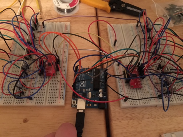
I'm using two multiplexers to control multiple rope strands. Here's roughly what that looks like:

enter image description here

I'm still a bit new to electronics prototyping (coming from software development); so I'm not sure if what I want to do is possible with a multiplexer

Happy to start offer a bounty to a helpful answer.

Thank you

5
  • 3
    This is going to be difficult! You should have bought a digital LED strip. The analog one you got needs to be continously fed with PWM signals, and the MUXes can only route your PWM output to one color channel of one strand at a time. Are you using PNPs or MOSFETs? With MOSFETs, it may be possible to use their gate capacitance (or an extra cap) to hold the value while you rapidly cycle the MUX. Not sure you can do this fast enough to avoid visible blinking though. Commented Apr 8, 2017 at 7:35
  • Ah - that makes sense. Yeah, definitely should have gone with the digital LED strip :/ Wondering if something like this may do the trick... adafruit.com/products/1429
    – narner
    Commented Apr 8, 2017 at 12:52
  • 1
    Looks good to me. Notice that you will need pullup resistors between that chip and each of your transistors. Commented Apr 8, 2017 at 18:09
  • 1
    I would think that for a small number of channels, cycling through them wouldn't produce flicker, but 16 or more channels is a lot for that technique, especially if you want a fair amount of control over the brightness as opposed to just on/off. Another board to look at that might help out is the SX1509, which is cheaper and I think more programmable than the TLC5947.
    – cjs
    Commented Apr 9, 2017 at 16:26
  • I advice using ht16k33 (you will use this one with digitalWrite)
    – user30878
    Commented Feb 14, 2018 at 7:52

1 Answer 1

1

Even I am new to this and I also find it a bit challenging with the available setup and desired output. Though it seems tough, I want you to just try out this code (it is a little modification to the one posted by you) and check whether it matches the expected result.

    //Mux control pins
#define s0 8;
#define s1 9;
#define s2 10;
#define s3 11;

//Mux in "SIG" pin
#define SIG_pin 3;

#define testValue 255;  //maximum value for analogWrite() function

void setup()
{
  pinMode(s0, OUTPUT); 
  pinMode(s1, OUTPUT); 
  pinMode(s2, OUTPUT); 
  pinMode(s3, OUTPUT); 

  pinMode(SIG_pin, OUTPUT);

  digitalWrite(s0, LOW);
  digitalWrite(s1, LOW);
  digitalWrite(s2, LOW);
  digitalWrite(s3, LOW);
}

void loop()
{
  //Loop through and read all 16 values
  for(int i = 0; i < 16 ; i ++)
  {
    delay(1000);
    writeMux(i);
  }
}


int writeMux(int channel)
{
  int controlPin[] = {s0, s1, s2, s3};

  int muxChannel[16][4]=
  {
    {0,0,0,0}, //channel 0
    {1,0,0,0}, //channel 1
    {0,1,0,0}, //channel 2
    {1,1,0,0}, //channel 3
    {0,0,1,0}, //channel 4
    {1,0,1,0}, //channel 5
    {0,1,1,0}, //channel 6
    {1,1,1,0}, //channel 7
    {0,0,0,1}, //channel 8
    {1,0,0,1}, //channel 9
    {0,1,0,1}, //channel 10
    {1,1,0,1}, //channel 11
    {0,0,1,1}, //channel 12
    {1,0,1,1}, //channel 13
    {0,1,1,1}, //channel 14
    {1,1,1,1}  //channel 15
  };

  //loop through the 4 sig
  for(int i = 0; i < 4; i ++)
  {
    digitalWrite(controlPin[i], muxChannel[channel][i]);
  }

  //read the value at the SIG pin
  for(int i_testValue = 0; i_testValue < testValue; i_testValue++)
  {
    analogWrite(i_testValue, SIG_pin);      //incresing intensity slowly with delay of 100ms
    delay(100);
  }


  //return the value
  return 0;
}

Your Answer

By clicking “Post Your Answer”, you agree to our terms of service and acknowledge you have read our privacy policy.

Not the answer you're looking for? Browse other questions tagged or ask your own question.