0

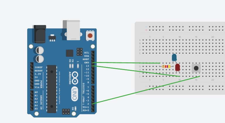
My circuit: enter image description here

My code:

// Pin 13 has a LED connected on most Arduino boards.
// give it a name:
int led = 13;
const int buttonPin = 2; // pushbutton connected to pin 2.

// the setup routine runs once when you press reset:
void setup() {
  // initialize the digital pin as an output.
  pinMode(led, OUTPUT);
  pinMode(buttonPin, INPUT);
}

// the loop routine runs over and over again forever:
void loop() 
{
  bool buttonState = digitalRead(buttonPin);
  while (buttonState == HIGH) // check while the button is pressed
  {
   digitalWrite(led, HIGH);   // turn the LED on (HIGH is the voltage level)
   delay(1000);               // wait for a second
   digitalWrite(led, LOW);    // turn the LED off by making the voltage LOW
   delay(1000);               // wait for a second
  }
}

What I wish to do is that when I press the button, the Led's start flashing and when I press them again, they stop blinking (like a fire alarm). Right now they do nothing and I dont know why. Is it something with the circuit or the code?

4
  • There is only one pin of the button connected to IO2. Is the other connection missing only in the diagram? Or is it missing in your actual circuit as well? Commented Feb 26, 2017 at 11:10
  • @DirkGrappendorf Yeah there is only one pin connected to pin 2. Why is that you need another one? and from where?
    – Utsav
    Commented Feb 26, 2017 at 11:12
  • I meant the other pin of the button. It is not connected to anything. See my answer. Commented Feb 26, 2017 at 11:39
  • Another pin of button must be connected with ground. That thing missing in your circuit. Provide ground to another pin of button and it's working fine with your code.
    – Hasan
    Commented Mar 3, 2017 at 11:34

1 Answer 1

1

The volatage level on the IO pin needs to change (from low to high and vice versa), only then can the microcontroller detect a button press. Without another connection to the button, IO2 is simply floating (unconnected).

There are two methods to implement this: external pull-up or external pull-down resistors and internal pull-up resistors (both methods are described for example in this tutorial).

I prefer the internal pull-up resitor method. You need to connect the second pin of the button to GND. Then change your setup code to

pinMode(buttonPin, INPUT_PULLUP);

If the button is not pressed, the internal pull up resistor inside the microcontroller pulls IO2 to +5V and a digitalRead(buttonPin) returns HIGH. When you press the button, IO2 is pulled to GND and digitalRead(buttonPin) returns LOW.

So in your case you need to check for a LOW reading, because you want the LEDs to blink when the button is pressed.

(Btw. you can replace the while loop with an if, since the loop() function is already executed in an infinite loop.)

Your Answer

By clicking “Post Your Answer”, you agree to our terms of service and acknowledge you have read our privacy policy.

Not the answer you're looking for? Browse other questions tagged or ask your own question.