I am fairly new to the Arduino topic and I'm trying to get a few things to work together.
At the moment I'm using an Arduino Uno board, but planning to use an Arduino Nano for this.
First I tried setting up a DC motor that can be controlled via PWM, which works perfectly when used standalone. I can start/stop the motor and change speed depending on the value I send to the PWM pin.
Next, I tried to use an RF-5V wireless receiver to work with a remote control from remote switched power outlets. For this one I followed the instructions on how to build a 433 MHz sniffer. This all by itself works as well. I can receive different codes depending on which keys on the remote I am pressing.
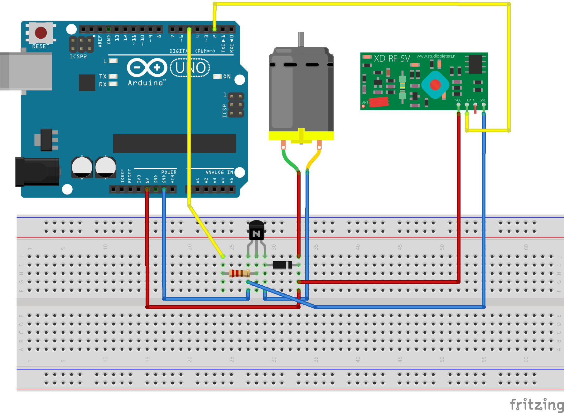
Now the fun part started: I wanted to integrate both projects into one, so I could use the remote to start/stop the motor. So I came up with the following circuit:
(The sketch is updated so it shows the right pins matching the code)
And the following code (which is partly from the instructions mentioned above):
#include <RCSwitch.h>

// init 433MHz lib
RCSwitch mySwitch = RCSwitch();
unsigned long lOldValue=0;  // to check for consecutive reads on 433MHz
int motorPin = 5; // PWM-Pin to use for motor

void setup() {
  pinMode(motorPin, OUTPUT);
  Serial.begin(9600);
  // set-up rf receiver
  mySwitch.enableReceive(0);
  // 433MHz Receiver on interrupt 0 => that is pin #2
}

void loop() {
  if (mySwitch.available()) {
    int value = mySwitch.getReceivedValue();
    // only react, if at least two times same value received
    if (value == lOldValue) {
      if (value == 0) {
        Serial.print("Unknown encoding");
      } else {
        Serial.print("Received ");
        Serial.print( mySwitch.getReceivedValue() );
        Serial.print(" / ");
        Serial.print( mySwitch.getReceivedBitlength() );
        Serial.print("bit ");
        Serial.print("Protocol: ");
        Serial.println( mySwitch.getReceivedProtocol() );
        // One of the keys on the remote
        if (value == 274393) {
          Serial.println("got start code, starting motor");
          analogWrite(motorPin, 100); // start the motor
        }
        // another key on the remote
        if (value == 270384) {
          Serial.println("got stop code, stopping motor");
          analogWrite(motorPin, 0); // stop the motor
        }
      }
    }
    lOldValue = value;
    mySwitch.resetAvailable();
  }
}
When I run the code and click on the remote, I get different values shown depending on the key I press. So the wireless receiver works as expected.
When I receive the right value for starting the motor, the motor really begins to turn, so this works as well.
And here the fun part starts:
As soon as I use the analogWrite function to send data to the PWM port the motor is connected to, the wireless receiver stops working (or at least I do not get any more values when pressing a key on the remote).
I found a few similar posts/problem descriptions on the net which said to try the following:
- Use another pin for PWM (due to possible interrupt conflicts). I tried that as well, same behaviour.
- Use external power supply instead of USB-Cable, which helped somebody resolve this issue. Not here. Does not work either.
So the question is:
Does anybody know how to combine those two things together so I can use the wireless receiver to get commands and switch on/off the motor with it on an Arduino Uno?
And would this solution probably work with an Arduino Nano as well?
Update:
I changed the motor against a LED, same behaviour. So its not related to the motor itself.
I found out that when i use some timers to set the motor pwm to 0 with the analogWrite function, that the wireless receiver starts working again. So it really looks like there is no way to use PWM and the wireless receiver together.
I also changed the pin for the receiver from 2 to 3 (and of course changed the code to use the right pin) and used other PWM pins for using with the motor. But still to no success.
Does anyone have an idea on how to bring both the wireless receiver and PWM driven things to work together? Might this be an hardware issue (due to interrupts) or a library issue for the rcswitch?

