3

I am trying to use the inbuilt ADC of the Arduino Due to measure voltage signals. The frequency range I'm interested in measuring is up to about 30 kHz.But I'm observing a strong capacitor behaviour as I increase the frequency ( from 10kHz onwards this is quite visible).

This is most visible when measuring a square wave. When I get close to 30 kHz the signal looks exactly like the text book capacitor charge/discharge wave and nothing like a square wave. Even at around 15 kHz, the square wave looks more like a sine wave/ ramp signal than a square wave.

Based on the behaviour my guess is that a capacitor in the Arduino Due ADC is causing this (as the frequency increases, the capacitor cannot charge/discharge fast enough). But I'm not sure whether I'm correct about this. Even if I'm correct, how can I fix this?

Any help would be much appreciated.

Thanks.

I don't have screenshots for the behaviour for a range of frequencies, but I will attach a hand drawing of what it looks like. enter image description here
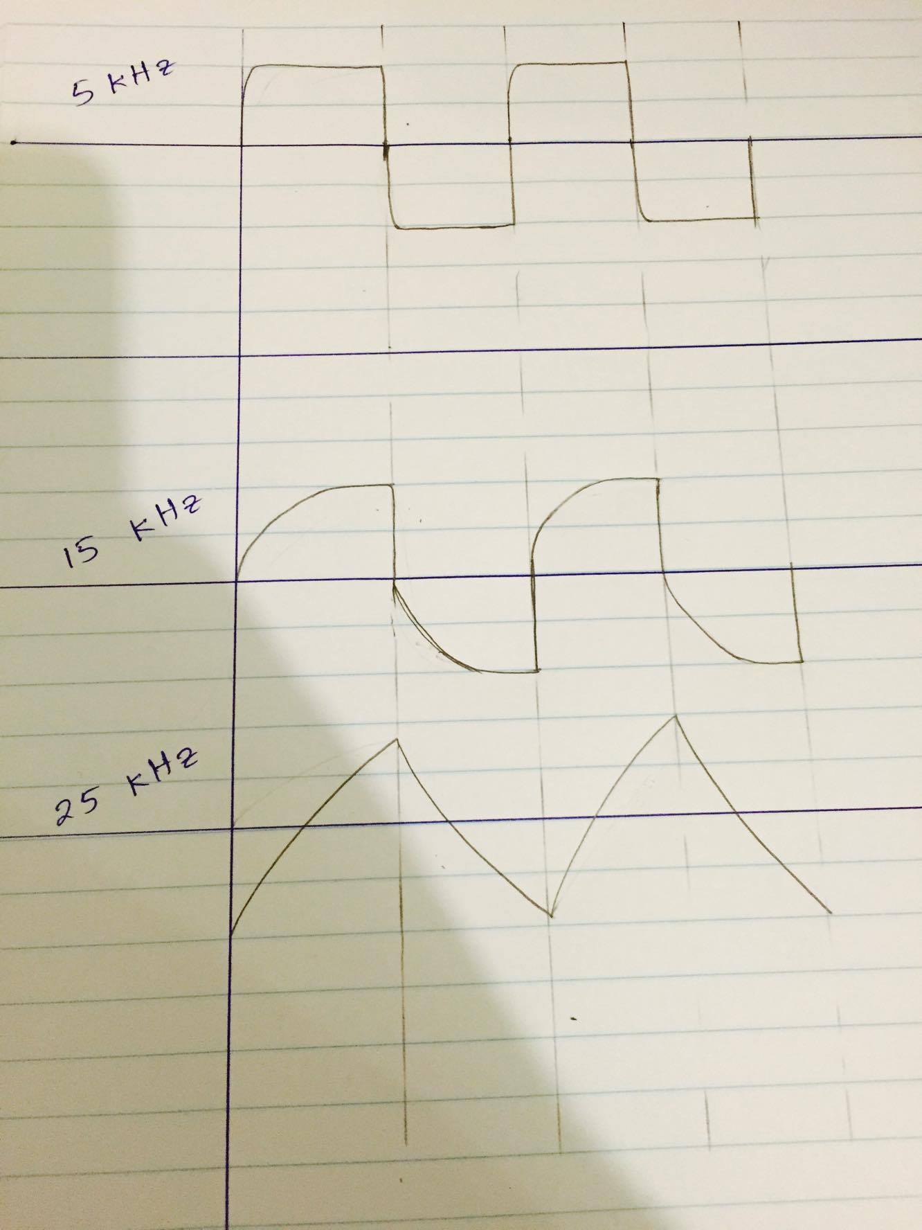
Also NOTE that As the frequency increases, the amplitude of the observed wave decreases ( I couldn't show this in my drawing). Think this again links back to the capacitor charge/discharge speed behaviour.

My Vin circuit : I tested by adding a voltage follower at the right most end(not shown on the schematic), but that made no difference.

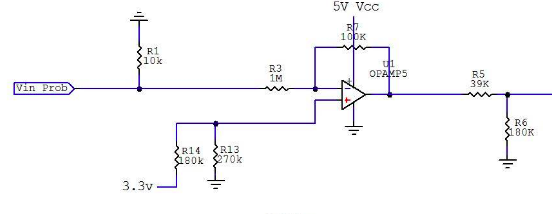
enter image description here

2
  • 1
    What is your signal source? If the source impedance is high, it is possible that capacitive loading is reducing the rise time, or your signal source itself has poor rise time. Show a plot where the distortion is less obvious too. My initial thought was aliasing, so do pay attention to the whole frequency range to rule that out. Commented Aug 2, 2016 at 7:56
  • I'm using a laboratory signal generator, so don't think that is the issue. And I am simultaneously measuring the signal using a laboratory DSO and it shows up perfectly as it is supposed to. I also updated my original post to show the behaviour for a range of frequencies.
    – acrox
    Commented Aug 2, 2016 at 8:30

2 Answers 2

1

Well, if you have source output impedance about 1k and Sample-And-Hold capacitance is 14pF, then RC time constant is about 14us.

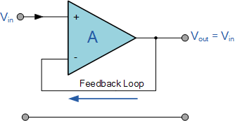
You need something with low output impedance. Non-inverting Voltage Follower would be perfect for this (see source):
enter image description here

6
  • I already have a Non-inverting follower op-amp in my input.
    – acrox
    Commented Aug 2, 2016 at 8:31
  • 2
    Which op-amp? It might be insufficient output impedance for this aplication.
    – KIIV
    Commented Aug 2, 2016 at 8:44
  • I think you might be correct. My input impedance to the ADC might be quite big because I have voltage divider resistors to allow for a bigger voltage range. I will try with a voltage follower right before the ADC input. BTW I'm using LM324 op-amp.
    – acrox
    Commented Aug 2, 2016 at 9:12
  • LM324 seems not be symetric in sink/source capabilities. But it shouldn't be this case, because your arduino chart seems to be symetric for charge and discharge.
    – KIIV
    Commented Aug 2, 2016 at 11:23
  • So I tested with the Voltage follower just before the input goes into the ADC, and it made absolutely no difference. I expected at least some improvement, but the signal did not change at all. I will attach my Vin circuit to the original post, it might be that the resistors I have used are just too high. But a voltage follower at the very end should have fixed that anyway. So still no progress.
    – acrox
    Commented Aug 3, 2016 at 3:03
1

Fixed : The issue was with the LM324 op-amp. It has a small slew rate (0.5 v/uS) which was causing the signal to flatten out at high frequencies. So had to change to an op-amp with a better slew rate.

Your Answer

By clicking “Post Your Answer”, you agree to our terms of service and acknowledge you have read our privacy policy.

Not the answer you're looking for? Browse other questions tagged or ask your own question.