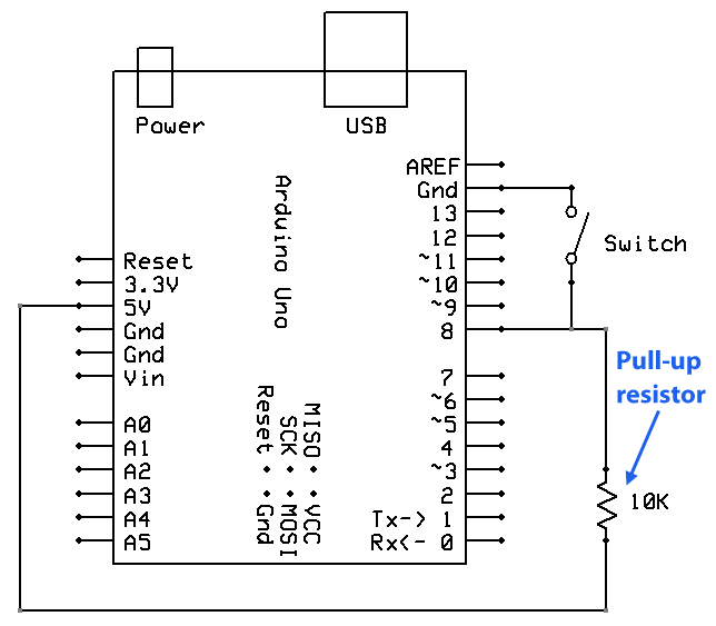
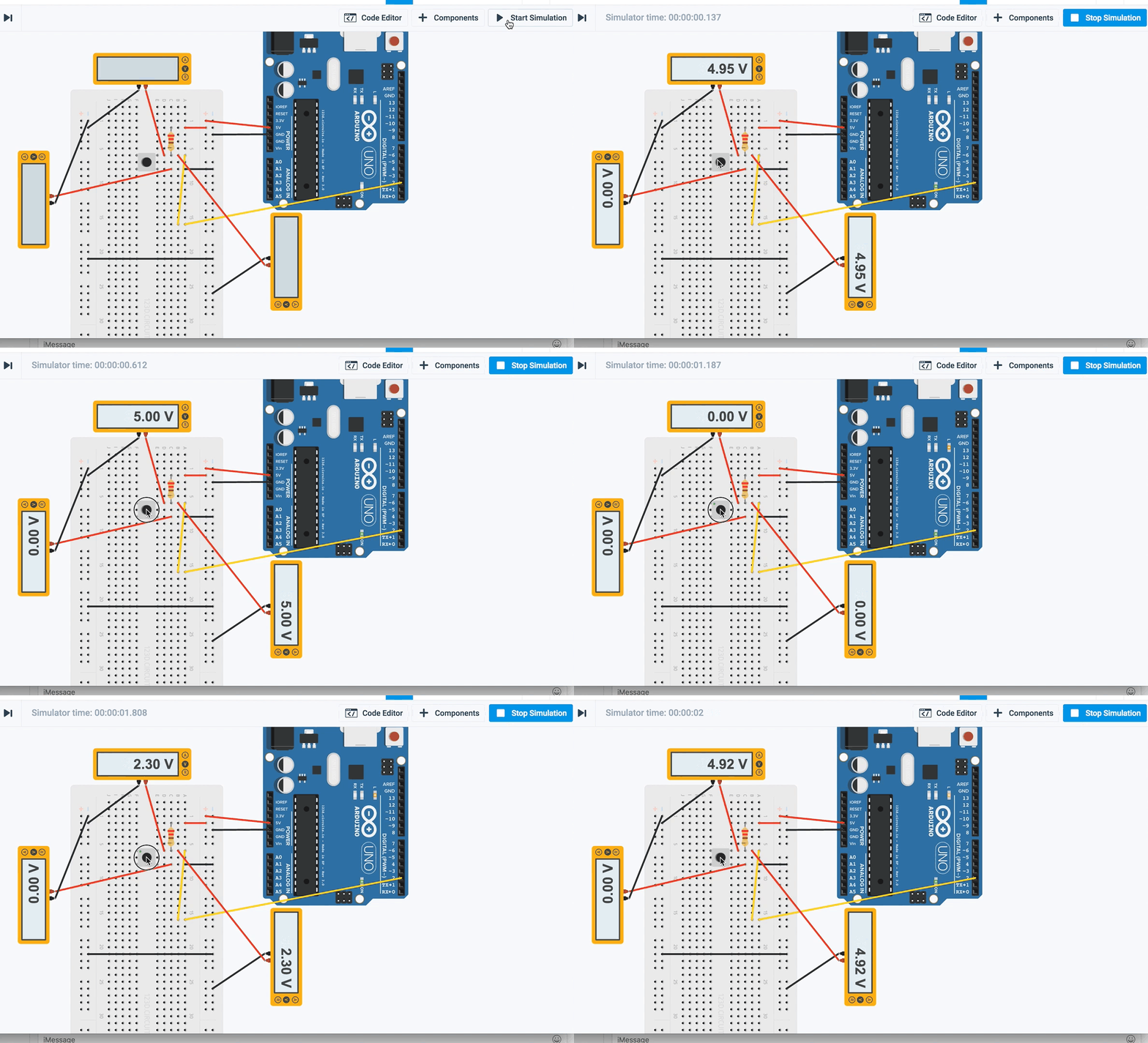
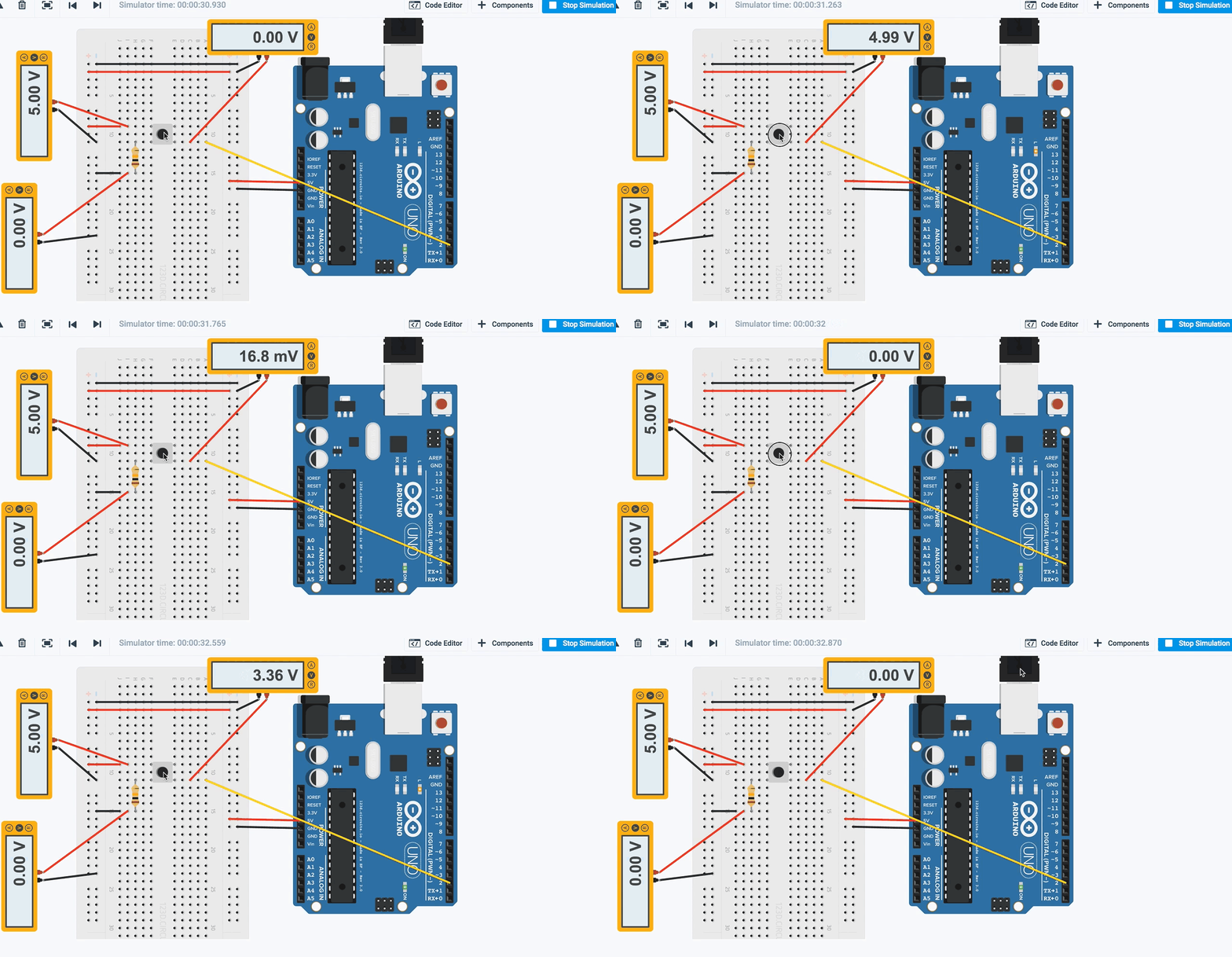
It's very hard to read your circuit, because there are wires everywhere. However this is effectively what a switch and a pull-up resistor looks like:

Due to the pull-up, pin 8 on the Arduino (which the switch is connected to) is normally pulled-up to 5V if the switch is open.
When you close the switch pin 8 becomes 0V, thus your meter reads 0V.
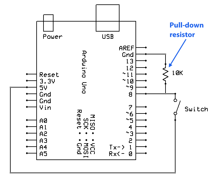
On the other hand, with a pull-down resistor, the circuit looks like this:

Now pin 8 is normally zero volts with the switch open, and when closed pin 8 is connected to 5V to pin 8 becomes 5V.
See my tutorial on switches for more details.
What happens with the flow of current and the resistor to make one example read high and the other low.
Imagine a door with a spring on it to close it. The spring is like a pull-up (or pull-down) resistor (depending on whether you are trying to keep the door closed or open).
The spring gently pulls the door shut. However if you barge out of it with a handful of pizzas in your hand your override the spring. In the absence of the spring the door would just flap in the breeze, sometimes opening and sometimes closing.
The point is, a person is strong enough to force the door open, despite the spring. Similarly if you close the switch you override the pull-up (or pull-down) resistor.
Where does the 5V go when the switch is closed.
It flows through the resistor to ground (or 5V depending on which one you are talking about).
When the switch is open in the pull up example - is voltage going through the resistor? From what I'm reading online, in the pull up case voltage isn't traveling through the resistor until the button is pressed.
Voltage doesn't "go through" a resistor, current does.
With the switch open, effectively a tiny amount of current goes through the resistor to pin 8. It is a "high impedance" input which means it puts a very small load on the input. Thus there is a very small voltage drop over the 10k resistor, and almost the full 5V is presented to the input pin for reading.
To work out the exact amount, we can look at the datasheet which says that the maximum leakage current through an I/O pin at 5V is 1 µA. Now using Ohm's Law we can find the voltage drop over the 10k resistor:
V = I * R
V = 0.000001 * 10000
V = 0.01 V
Thus with 5V at the 5V pin of the processor, and a (maximum of) 1 µA consumed at pin 8, it will therefore have 4.99 V at the pin, which therefore reads HIGH.
With the switch closed, then we use Ohm's Law to calculate the flow through the resistor:
I = V / R
I = 5 / 10000
I = 0.0005 A
Thus 0.5 mA flows through the resistor with the switch closed. This is not enough to damage the resistor, or make a significant load on the 5V line.
I think you are getting confused (as I did when I was young) that a big resistance (like 10k) must "resist" a lot of voltage. It is easy to think that after going through 10k resistance there can't be much "voltage" left.
The fact is, though, that the voltage on the other end of a resistor is proportional to not only the resistance (R) but also the current (I). This is Ohms's Law (V = I * R)
So, if the current is very small (as is the case with an input pin) then the voltage drop over a resistor - even a large one - is very small.
So, the idea of a pull-up resistor is, that with no external influences (like a switch) then after passing through 10k resistance, there is still 5V at the other side.
Let me issue you with a challenge. Find a voltage source (eg. a battery). Measure it with your multimeter. Let's say you have a 5V source which is the Arduino 5V pin. Now get a 10k resistor. Put it in series with the 5V source. Now measure it on the other side of the resistor. Depending on the quality of the meter (and thus how much current it takes to measure a voltage) you will get very close to the same voltage reading. In my case I had 5V on one side of the resistor, and 4.99V on the other side. This is exactly what my calculations above predicted.


