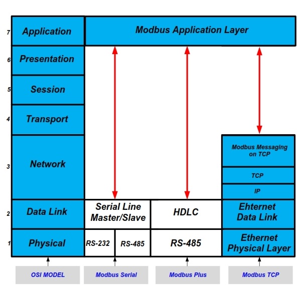
Modbus TCP simply put is a Modbus packet wrapped in a TCP packet.
There is no 'additional layer of Modbus' added on top. If we look at the osi model pictured below you can see there is only one Modbus application layer (i.e modbus slave/server)

Essentially if the wifi->RS485 gateway strips the payload from the TCP packets and simply spits it out the serial side then no modifications are necessary (apart from the obvious RS485 transceiver you will need to interface the arduino with the gateway).
What you will need to make sure is that the gateway will only send packets directed to port 502 to the arduino (502 is the Modbus TCP port) as it is possible other IP traffic could cause some drama for the modbus slave.
Additionally, you will have to ensure that you set the slave ID of the arduino to be what is specified by the master. Are you also building the Modbus TCP client? If not it is very possible that the required slave ID is 255 which is not supported by the modbus library you have linked.
Modbus (serial) slave IDs can only be between 1 and 247 for traditional reasons when Modbus was first standardised as it was only envisioned to be on serial, however when Modbus TCP was introduced an additional addressing layer (TCP / IP) meant that the unit ID (slave ID when using Modbus TCP) could be anything from 0 - 255. It is common for some vendors (at least in industrial automation) to use a unit ID of 255 for standard Modbus transactions scanning IO and diagnostic or configuration transactions to be send to other unit IDs (essentially making the TCP server a modbus router, forwarding packets to one of the multiple Modbus servers running on that single slave device)

