2

I have a little clock with a button on it that i need to push four times every second hour. I am trying to get the arduino micro to do it for me.

I am trying to figure out how to connect the arduino to trigger it. The clock is operated by a CR2 (3.0V) cell battery. Is there a way to do this without a transistor? If not what do i need? How can i find out how much amp my circuit requires?

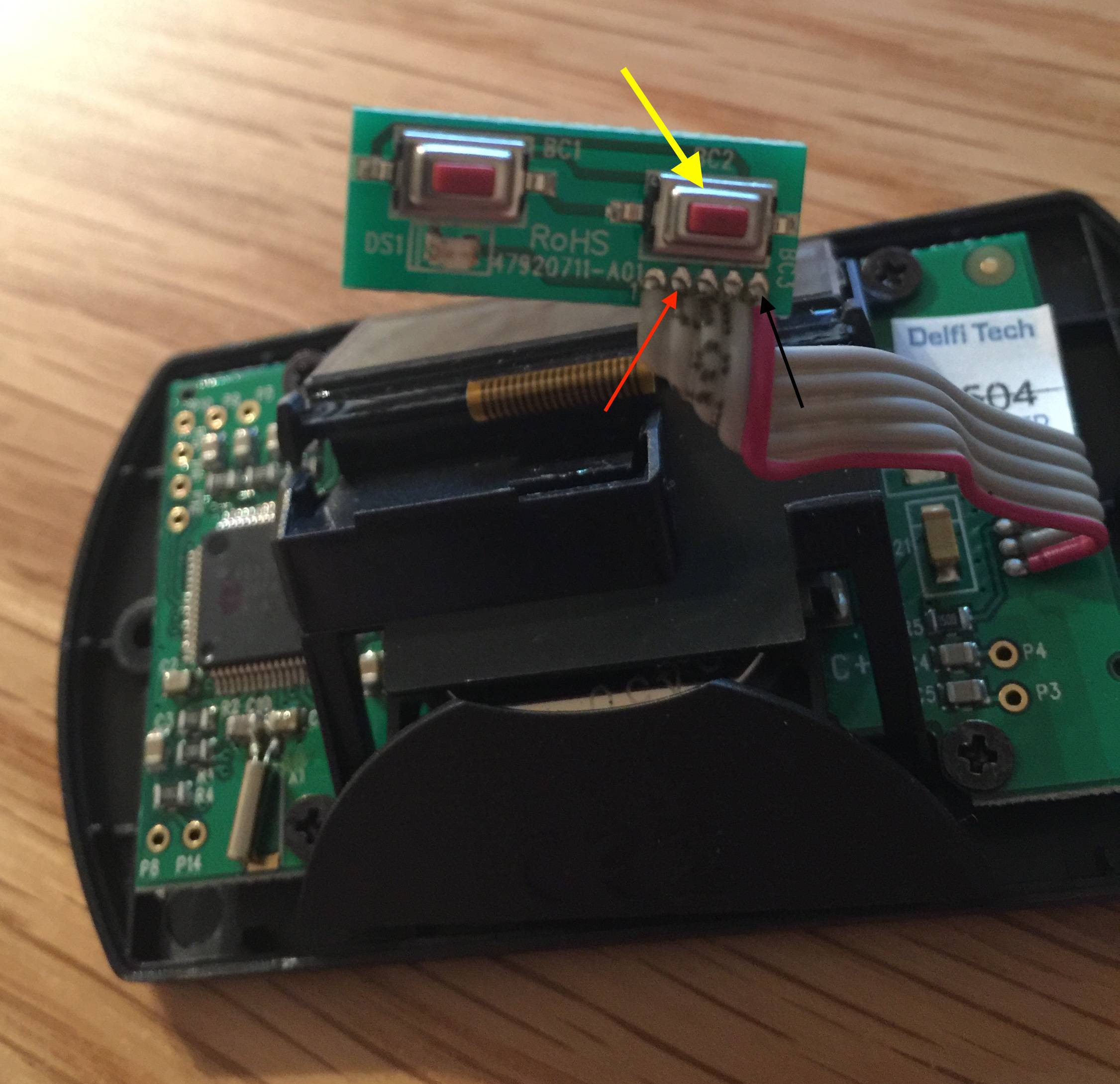
The red arrow is pointing on the cable i think triggers the clock, and i think the black arrow is pointing on the cable that is the clock gnd.

(edit: I have found similar questions explaining the process with transistor, but not without..)

Picture of the button that i need to push

6
  • 2
    What happens if you do not push the button four times every second hour? Commented Feb 13, 2016 at 0:50
  • This might be answerable by someone who has the same model of clock to test, but its otherwise unlikely unless you add a bunch of information. Eg: What brand and model is it? Is it battery operated? What's the battery voltage if so? Do you have a digital voltmeter to take measurements? Do you have an oscilloscope to look at waveforms? By "black cable is the clock gnd", do you mean the red wire with a black arrow pointing to it, or do you mean that bit that appears to be a black wire next to a gray wire, near test point P14 at lower left? Commented Feb 13, 2016 at 1:46
  • The voltage of the battery is 3.0V. "black cable" should be "black arrow". I have a digital voltmeter and when a push the button with the yellow arrow it is connection between the the cables that i have pointed out with arrows. Commented Feb 13, 2016 at 9:09
  • Guess an opto-isolator could work. en.wikipedia.org/wiki/Opto-isolator Commented Feb 13, 2016 at 9:33
  • @MikaelPatel Have you never watched Lost? Commented Feb 13, 2016 at 13:11

3 Answers 3

0

You might try attaching an Arduino IO through a resistor to pin 4 (where your red arrow points), and Arduino ground to pin 1 (where your black arrow points). Because the clock is battery-operated, you can connect its ground to the Arduino's ground without problem.

Before attaching the Arduino, use your DVM to measure the voltage between pins 4 and 1, with the switch open and with the switch closed. In following, I'll suppose you have measured 3V when the switch is open and 0V when it's closed. This would indicate that the clock's circuit pulls or drives pin 4 high when the switch is open. In initial experiments, I'd start with a 1KΩ or so resistor (eg, any resistor between 500Ω and 2000Ω) in series with an ammeter and the Arduino IO. If you measure at most a few microamps of current in both the “switch open” and “switch closed” cases (see below) then the circuit should function ok with the resistor in place (since there will be only a tiny voltage drop across it). [If, on the other hand, you measure several milliamps of current in either case, then my ideas about the clock circuit might not apply; in which case you might need an optoisolator or relay.]

To represent switch operation, put the Arduino IO into INPUT mode to represent an open switch, and into OUTPUT LOW to represent a closed switch. For example, in setup() say

pinMode(ClockPin, INPUT);  // Also does digitalWrite(ClockPin, LOW);

and in your loop() say stuff like

if (TheTimeHasCome) {
   for (int k=0; k<4; ++k) {
      pinMode(ClockPin, OUTPUT);  // Presses the button
      delay(50);                  // Holds the button
      pinMode(ClockPin, INPUT);   // Releases the button
      delay(50);                  // Wait between buttons
   }

The comment // Also does digitalWrite(ClockPin, LOW); is a reminder that pinMode(ClockPin, INPUT); has two actions: it sets ClockPin to be an input instead of an output, and takes the corresponding PORTx bit low (ie, resets a bit in PORTB, PORTC, PORTD, or whatever). If we had said pinMode(ClockPin, INPUT_PULLUP);, then the corresponding PORTx bit would have been set high, and the pin would be weakly pulled to Vcc, eg +5V. It would be a mistake to send 5V to the clock, as it's likely that would exceed its voltage tolerance.

Since pinMode(ClockPin, INPUT); leaves the appropriate PORTx bit low, there is no need to use digitalWrite() separately in the sketch. When ClockPin is an input, its high impedance allows the clock to pull pin 4 high; when ClockPin is an output, its 0 level connects pin 4 to pin 1.

0

Yes, This can be achieved without a transistor.

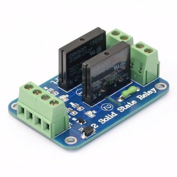
As the circuits would be on isolated power supplies: Arduino circuit on one and the clock on another, you can use a Solid State Relay.

SSR

Use the relay with your Arduino (5v or 3.3v) and wire the relay contacts parallel to the clock switch. This will isolate any power issues as clock will be powered with its own power and Arduino will be powered with its own.

You can program Arduino with proper delays to actuate the relay accordingly.

Hope this helps.

2
  • 1
    Very few relays will have a coil current low enough to allow it to be powered directly from an Arduino - you'll need a transistor for the relay. Commented Feb 13, 2016 at 13:13
  • @CharlieHanson thanks for the pointer; a SSR is also a relay. I'll update my answer. Commented Feb 13, 2016 at 23:06
0

Connect the Arduino and your clock grounds together. Get a small resistor - no less than 1 kOhm - and connect your VOM (in current mode) in series with the resistor and your Arduino output pin. Set the output pin to LOW and observe Did the clock reset? What was the current on your VOM? If the clock reset and the current was more than 20 mA get a bigger ( 10 kOhms ) resistor and try it again. If the clock reset and your current was less than 20 mA you are done.

And if you really want to isolate the clock from Arduino use low current LED and connect the cathode to the output pin and anode to the clock. Keep the resistor in the circuit.
Than you will also have an indicator of "circuit is active".

Your Answer

By clicking “Post Your Answer”, you agree to our terms of service and acknowledge you have read our privacy policy.

Not the answer you're looking for? Browse other questions tagged or ask your own question.