1

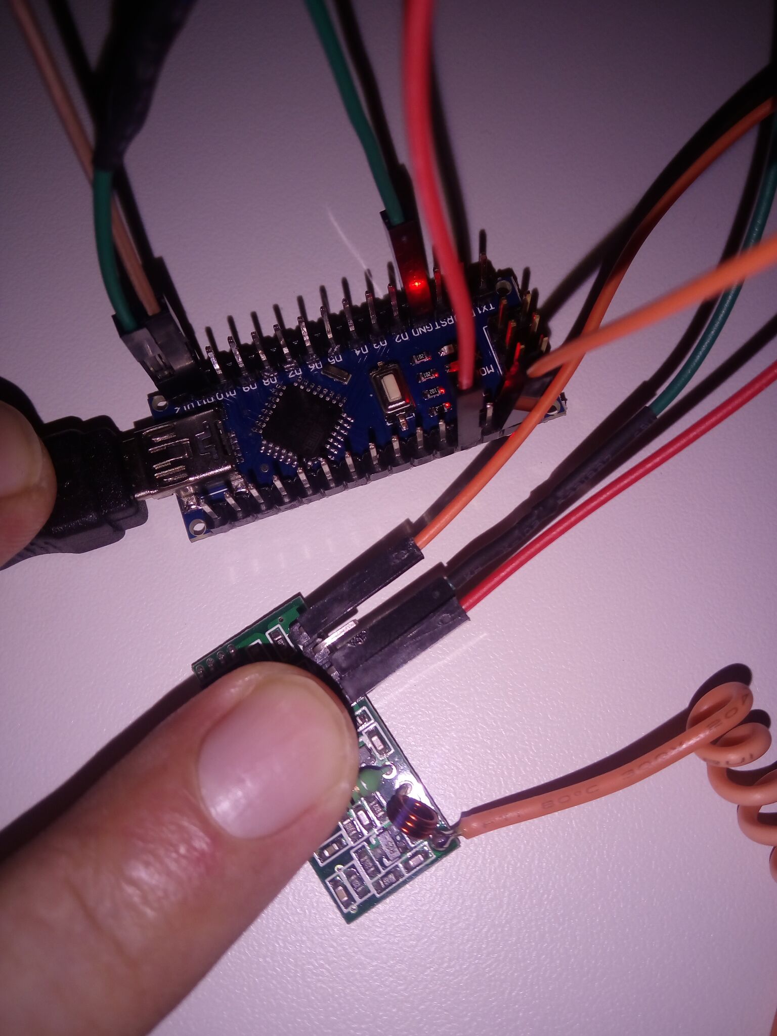
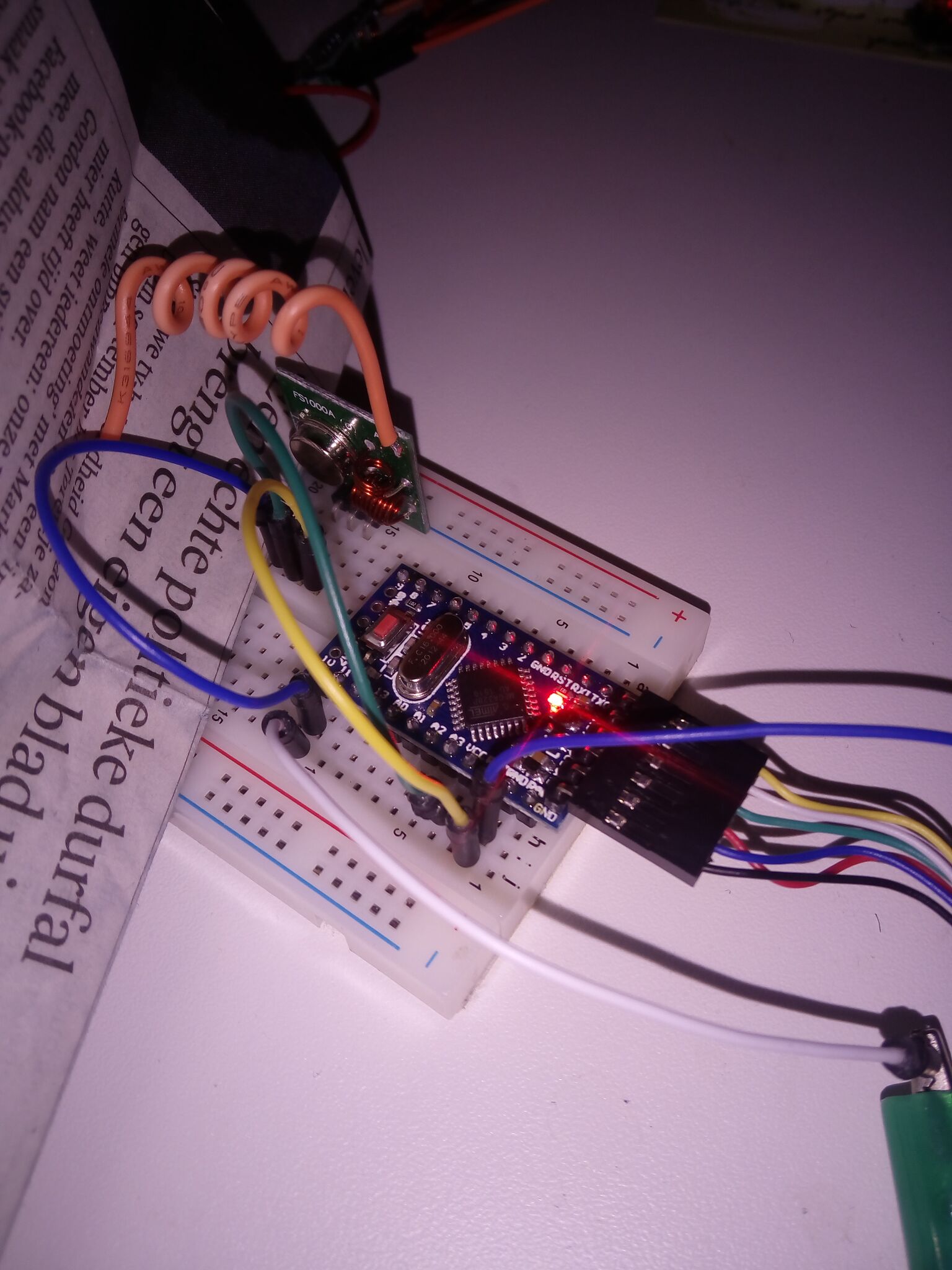
I'm trying to send data using these cheap parts. When I check the voltage on the data port of the transmitter, I see what I expect, 1.2 and 0.6 fluctuating while sending. But when I check the receiver I get 0. I've got 3 of the sets and tried them all. Also tried it with running the transmitter on 11V for some extra power. I've added a LED to the transmitter to see when it transmits and I've added a not-so-good antenna to both while they are only 5cm apart during my tests.

Any advice would be appreciated.

Receiver
FS1000A with a LR433A

#include <VirtualWire.h>

const int led_pin = 6;
//const int transmit_pin = 12;
const int receive_pin = 11;
//const int transmit_en_pin = 3;

void setup()
{
    delay(1000);
    Serial.begin(9600);  // Debugging only
    Serial.println("setup");

    // Initialise the IO and ISR
    //vw_set_tx_pin(transmit_pin);
    vw_set_rx_pin(receive_pin);
    //vw_set_ptt_pin(transmit_en_pin);
    //vw_set_ptt_inverted(true); // Required for DR3100
    vw_setup(1000);  // Bits per sec

    vw_rx_start();       // Start the receiver PLL running
}

void loop()
{
    uint8_t buf[VW_MAX_MESSAGE_LEN];
    uint8_t buflen = VW_MAX_MESSAGE_LEN;

    if (vw_get_message(buf, &buflen)) // Non-blocking
    {
  int i;

        digitalWrite(led_pin, HIGH); // Flash a light to show received good message
  // Message with a good checksum received, print it.
  Serial.print("Got: ");

  for (i = 0; i < buflen; i++)
  {
      Serial.print(buf[i], HEX);
      Serial.print(' ');
  }
  Serial.println();
        digitalWrite(led_pin, LOW);
    }
}

Transmitter

#include <VirtualWire.h>

const int led_pin = 11;
const int transmit_pin = 12;
const int receive_pin = 2;
const int transmit_en_pin = 3;

void setup()
{
  // Initialise the IO and ISR
  vw_set_tx_pin(transmit_pin);
  vw_set_rx_pin(receive_pin);
  vw_set_ptt_pin(transmit_en_pin);
  vw_set_ptt_inverted(true); // Required for DR3100
  vw_setup(1000);   // Bits per sec
}

byte count = 1;

void loop()
{
  char msg[7] = {'h','e','l','l','o',' ','#'};
  Serial.println("sending");
  msg[6] = count;
  digitalWrite(led_pin, HIGH); // Flash a light to show transmitting
  vw_send((uint8_t *)msg, 7);
  vw_wait_tx(); // Wait until the whole message is gone
  digitalWrite(led_pin, LOW);
  delay(1000);
  count = count + 1;
}

transmitter receiver

1
  • bro based on (You should be able to power the receiver + and GND I have one, which ran on 5v, I can't see if these are the same, and put a multimeter from GND to Data, and you should get about half of Vcc, ) he say the problem is not with the module the problem is with the library
    – nitra ss
    Commented May 9, 2022 at 14:35

2 Answers 2

3

If you are not getting anything on the receiver, then the receiver is definitely the problem. These units will boost the gain until it get some signal, any signal.

You should be able to power the receiver + and GND (I have one, which ran on 5v, I can't see if these are the same), and put a multimeter from GND to Data, and you should get about half of Vcc, probably fluctuating a bit. If you look at the same with an oscilloscope, it should fluctuating wildly between 0 and Vcc volts. All of this should work without a transmitter, and without an Arduino (you will need a power supply for the receiver).

Note: this is from memory, I don't have mine here to test.

Once you are getting "random data" (background noise), you can progress to sending a signal.

Note that you should keep your "1"s and "0"s balanced to get a clear signal - check out Manchester encoding (this encodes a "1" as "1,0", and a 0 as "0,1", so there will be a perfect balance). You might also want to send a 1010101010 at the start - this gives the receiver a chance to adjust the gain to the correct level. Or, you can use some width-based encoding (e.g. "slow 1, slow 0" for a "1", and "fast 0, fast 1" for a "0").

3
  • When I put the multimeter to Data and GND on the receiver, the result is 0 fluctuating to -0 and you expect to see 50% of the Vcc input so around 2.5 Volts? I'll ask around for an osciloscope as I don't have one myself. Thanks for the advice on the signal encoding, I hope I can get to that soon.
    – Thijs
    Commented Nov 13, 2015 at 6:50
  • I made a noob mistake as you can read below. Just wanted to let you know you are right about the half Vcc on the receiving Data+GND and thanks for your help.
    – Thijs
    Commented Nov 13, 2015 at 7:50
  • In case anyone else sees your above comment, -0 means there is 0 volts flowing in the other direction. This is not uncommon when there is no power flowing through the wires, little random fluctuations will cause this. If there are less than -0 (e.g. -2.5volts), it means the power is flowing in the other direction (or you have the probes on your multimeter around the wrong way). Commented Nov 15, 2015 at 19:44
2

What I thought was the receiver turned out to be the transmitter. I've earned my noob medal now :) The chip with the LR433A on it is the sending unit.

The code above and the wiring is all good!

2
  • I will, I have to wait a day to do that :)
    – Thijs
    Commented Nov 13, 2015 at 12:34
  • 1
    Congratulations on your medal - I have a a pile of them this high ^ Commented Nov 15, 2015 at 19:33

Your Answer

By clicking “Post Your Answer”, you agree to our terms of service and acknowledge you have read our privacy policy.

Not the answer you're looking for? Browse other questions tagged or ask your own question.