0

My kids have a few odd inexpensive toys with a soft push-button that will turn on the toy, and subsequent pushes change the toy's mode of operation in some fashon. A flashlight comes to mind, where the button is pushed once and it turns on, push again and it blinks, and a 3rd time and the light turns off.

I've looked inside one of these flashlights, and there's a small blob covering some IC, what looks to be a diode, and the usual connections for the batteries and lights.

How do these circuits "work" without immediately draining the batteries? I'm looking to mimic this behaviour on a battery powered arduino Uno (or possibly Pro Mini).

What comes to mind is that the button is on an interrupt line, which wakes the system up from some sleep state.. when the button cycles around to an "off" state, the system goes back to sleep.

2 Answers 2

1

I have a lengthy write-up about saving power at Power saving techniques for microprocessors.

One of the sample sketches on that page (Sketch J) does what you ask:

#include <avr/sleep.h>

const byte LED = 9;

void wake ()
{
  // cancel sleep as a precaution
  sleep_disable();
  // precaution while we are doing other things
  detachInterrupt (0);
}  // end of wake

void setup () 
  {
  digitalWrite (2, HIGH);  // enable pull-up
  }  // end of setup

void loop () 
{

  pinMode (LED, OUTPUT);
  digitalWrite (LED, HIGH);
  delay (50);
  digitalWrite (LED, LOW);
  delay (50);
  pinMode (LED, INPUT);

  // disable ADC
  ADCSRA = 0;  

  set_sleep_mode (SLEEP_MODE_PWR_DOWN);  
  sleep_enable();

  // Do not interrupt before we go to sleep, or the
  // ISR will detach interrupts and we won't wake.
  noInterrupts ();

  // will be called when pin D2 goes low  
  attachInterrupt (0, wake, FALLING);

  // turn off brown-out enable in software
  // BODS must be set to one and BODSE must be set to zero within four clock cycles
  MCUCR = bit (BODS) | bit (BODSE);
  // The BODS bit is automatically cleared after three clock cycles
  MCUCR = bit (BODS); 

  // We are guaranteed that the sleep_cpu call will be done
  // as the processor executes the next instruction after
  // interrupts are turned on.
  interrupts ();  // one cycle
  sleep_cpu ();   // one cycle

  } // end of loop

According to when I tested that, it used 0.116 µA when asleep (116 nA). That is well below the rate at which batteries self-discharge.

Basically that code does what you described. It sleeps, when pin D2 goes low it wakes and flashes an LED.

I should point out though that any "development board" Arduino with a voltage regulator, USB interface, and power LED on it will consume considerably more power because of the current drain they consume.

For low-power applications you need the bare chip (with appropriate supporting circuitry, like decoupling capacitors).

3
  • Long time fan of your powersaving page, have posted it as an answer to many a question here :) Commented Jul 23, 2015 at 1:22
  • 1
    Thanks! I actually improved the above code today. First, I changed the LOW interrupt to FALLING, as we now know that a FALLING interrupt will wake the processor. And FALLING is better because if you hold the button down you don't get multiple interrupts. Also, I re-measured the idle power. My page had it as 0.35 µA, but with better testing equipment I now measure 0.116 µA. That's pretty low. :)
    – Nick Gammon
    Commented Jul 23, 2015 at 3:09
  • Wow, thanks! Quite a comprehensive write-up on your site. I'll do some learnin' on using a bare chip, instead of the Pro Mini or other boards. Thanks again!
    – Tim
    Commented Jul 23, 2015 at 13:35
0

I have made a circuit in the past that does more or less this:
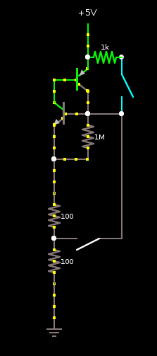
Latch Circuit

There are two switches in the diagram - the one on the top right turns the circuit on, and the one lower-middle turns it off. Once turned on, it will stay on until the bottom switch is pressed.

The two resistors bottom left, and the switch at the bottom, represent your Arduino.

Note that, this diagram is OUTSIDE the arduino - it provides power TO the Arduino (and any other components relating to your project). That is, the bottom of the 1MOhm resistor, and the bottom of the left transistor, connect to the power pin on the Arduino. Those two resistors don't literally, exist.

It works as follows: The transistors do pretty much all the work. Both transistors work as switches. At the start (as shown in the diagram), both transistors have the same voltage at the base, and the emitter (the top one +5v between top and center/left; the bottom one 0v between center/right and bottom). This turns both switches off, and preserves the status quo, and consuming nearly no power.

As soon as the switch at the top is closed, the base (center/right) of the lower transistor is pulled up to +5V, switches this transistor on, and power can flow from this collector to the emitter. This means power can flow through the TOP transistor from emitter (top) to base (center/left), switching on the TOP transistor. This allows power to flow from the emitter (top) to collector (bottom). This takes over from the pushbutton, keeping the bottom transistor on. This is the other stable state.

At this point, power goes to the Arduino (bottom two resistors, representing load, and bottom switch, which is one of the pins on the Arduino. This pin should be set to "high impedance" until the Arduino wants to switch itself off, then it should go low.

I built the top part of the circuit, with an LED for the bottom half (both switches were just wires), and it worked, but I'd have to consider what would happen if the arduino pin is high or low while the top button is being pressed.

7
  • Interesting. Can you measure the idle power consumption?
    – Nick Gammon
    Commented Jul 23, 2015 at 3:11
  • Don't know how. All the power for everything runs through the top transistor, so I guess it would be the leakage on an transistor at cutoff? On the other side of it, when powered up, it should run emitter -> collector through the top transistor, then through the base of the lower transistor, so there should be no resistance. I don't know how it would work in practice when switching on/off, and what happens when both switches are closed - I guess the resistor at the top would protect it? Commented Jul 23, 2015 at 4:15
  • The disadvantage of this technique is that it requires an external signal to activate it, since the arduino (or whatever else) gets NO power at all until fired up. Commented Jul 23, 2015 at 4:17
  • Don't know how. - set the whole thing up, then instead of connecting your power supply to the 5 V input point, connect via your multimeter in milliamps range. If you aren't sure of the technique, Google how to do current measurements - you don't want to blow the fuse in your meter.
    – Nick Gammon
    Commented Jul 23, 2015 at 5:03
  • I know how to measure power consumption, and I will try it, but my simulator shows in the picoamps. I guess the leakage of the top transistor at cutoff? I will experiment with my simulator when I get a chance. My simulator says the above circuit (off) leaks 15pA. Commented Jul 23, 2015 at 21:16

Your Answer

By clicking “Post Your Answer”, you agree to our terms of service and acknowledge you have read our privacy policy.

Not the answer you're looking for? Browse other questions tagged or ask your own question.