0

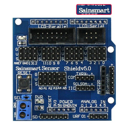
I have a mpu6050(which I got from here http://www.sainsmart.com/sainsmart-mpu-6050-3-axis-gyroscope-module.html) and I have connected it to special ports on a sensor shield made for the mpu6050(http://www.amazon.co.uk/SainSmart-InstaBots-SS-SBR-1-0-Sensor-Shield/dp/B00N1YANH2) which is on a Arduino uno. I have a sketch which is meant to print stuff out to the serial monitor, however when the mpu6050 is attached nothing is printed out and when it is not attached the Arduino does print out things to the serial monitor. I attached other things to the sensor shield and things were printed out on the serial monitor, so I know it is the mpu6050 that is the problem.

This is my code

#include <Wire.h>
#include <SPI.h> 
#include <Mirf.h>
#include <nRF24L01.h>
#include <MirfHardwareSpiDriver.h>
#include <I2Cdev.h>
#include <MPU6050.h>

MPU6050 accelgyro;
int16_t ax, ay, az;
int16_t gx, gy, gz;

#define Gry_offset 0 
#define Gyr_Gain 0.00763358  
#define Angle_offset 4
#define RMotor_offset 20
#define LMotor_offset 20
#define pi 3.14159 

long data;
int x, y;
float kp, ki, kd; 
float r_angle, omega;
float f_angle;
float Turn_Speed = 0, Turn_Speed_K = 0;
float Run_Speed = 0, Run_Speed_K = 0, Run_Speed_T = 0;
float LOutput,ROutput;

unsigned long preTime = 0;
float SampleTime = 0.08;
unsigned long lastTime;
float Input, Output;
float errSum, dErr, error, lastErr;
int timeChange; 

int TN1=3;
int TN2=4;
int ENA=9;

int TN3=5;
int TN4=6;
int ENB=10;

void setup() {
  Wire.begin();
  accelgyro.initialize();
  pinMode(TN1,OUTPUT);
  pinMode(TN2,OUTPUT);
  pinMode(TN3,OUTPUT);
  pinMode(TN4,OUTPUT);
  pinMode(ENA,OUTPUT);
  pinMode(ENB,OUTPUT);

  Mirf.spi = &MirfHardwareSpi;   
  Mirf.init();
  Mirf.setRADDR((byte *)"serv1");
  Mirf.payload = sizeof(long);
  Mirf.config();
  Serial.begin(115200);
  Serial.print("Hello");
}

void loop() {
  Recive();
  accelgyro.getMotion6(&ax, &ay, &az, &gx, &gy, &gz);
  r_angle = (atan2(ay, az) * 180 / pi + Angle_offset);
  omega =  Gyr_Gain * (gx +  Gry_offset);  
  //Serial.print("  omega="); Serial.print(omega);
  if (abs(r_angle)<45){
    myPID();
    PWMControl();
  }
  else{
    analogWrite(ENA, 0);
    analogWrite(ENB, 0);
  }
}

void Recive(){
  if(!Mirf.isSending() && Mirf.dataReady()){
    Mirf.getData((byte *)&data);
    Mirf.rxFifoEmpty();

    y = data >> 16;
    x = data & 0x0000ffff;
    //Serial.print("  x="); Serial.print(x);
    //Serial.print("  y="); Serial.println(y);
    if(x >= 520){
      Run_Speed_K = map(x, 520, 1023, 0, 100);
      Run_Speed_K = Run_Speed_K / 50;
      Run_Speed = Run_Speed + Run_Speed_K;
    }
    else if(x <= 480){
      Run_Speed_K = map(x, 480, 0, 0, -100);
      Run_Speed_K = Run_Speed_K / 50;
      Run_Speed = Run_Speed + Run_Speed_K;
    }
    else{
      Run_Speed_K = 0;
    }
    if(y >= 520){
      Turn_Speed = map(y, 520, 1023, 0, 20);
    }
    else if(y <= 480){
      Turn_Speed = map(y,480,0,0,-20);
    }
    else{
      Turn_Speed = 0;
    }
  }
  else{
    x = y = 500;
  }
}

void myPID(){
  kp = analogRead(A0)*0.1;  
  //kp=17;
  Serial.print("  kp=");Serial.print(kp);
  kd = analogRead(A2)*1.0;  
  //kd=840;
  Serial.print("  kd=");Serial.print(kd);
  //ki = analogRead(A3)*0.001;  Serial.print("  ki=");Serial.print(ki);

  //kp = 0;  Serial.print("  kp=");Serial.print(kp);
  //kd = 0;  Serial.print("  kd=");Serial.print(kd);
  ki = 0.08;  
  Serial.print("  ki=");Serial.print(ki);

  unsigned long now = millis();
  float dt = (now - preTime) / 1000.0;
  preTime = now;
  float K = 0.8;
  float A = K / (K + dt);
  f_angle = A * (f_angle + omega * dt) + (1 - A) * r_angle; 

  Serial.print("  f_angle=");Serial.print(f_angle);


  timeChange = (now - lastTime);
  if(timeChange >= SampleTime){
    Input = f_angle;
    error = Input;
    errSum += error * timeChange;
    dErr = (error - lastErr) / timeChange;
    Output = kp * error + ki * errSum + kd * dErr;
    LOutput = Output + Run_Speed + Turn_Speed;  Serial.print("  LOutput=");Serial.print(LOutput);
    ROutput = Output + Run_Speed - Turn_Speed;  Serial.print("  ROutput=");Serial.println(ROutput);
    lastErr = error;
    lastTime = now;
  }
}

void PWMControl(){
  if(LOutput > 0){
    digitalWrite(TN1, HIGH);
    digitalWrite(TN2, LOW);
  }
  else if(LOutput < 0){
    digitalWrite(TN1, LOW);
    digitalWrite(TN2, HIGH);
  }
  else{
    digitalWrite(TN1, HIGH);
    digitalWrite(TN2, HIGH);
  }
  if(ROutput > 0){
    digitalWrite(TN3, HIGH);
    digitalWrite(TN4, LOW);
  }
  else if(ROutput < 0){   
    digitalWrite(TN3, LOW);
    digitalWrite(TN4, HIGH);
  }
  else{
    digitalWrite(TN3, HIGH);
    digitalWrite(TN4, HIGH);
  }
    analogWrite(ENA, min(255, abs(LOutput) + LMotor_offset));
    analogWrite(ENB, min(255, abs(ROutput) + RMotor_offset));
}

and this is a picture of the mpu6050 on the sensor shield
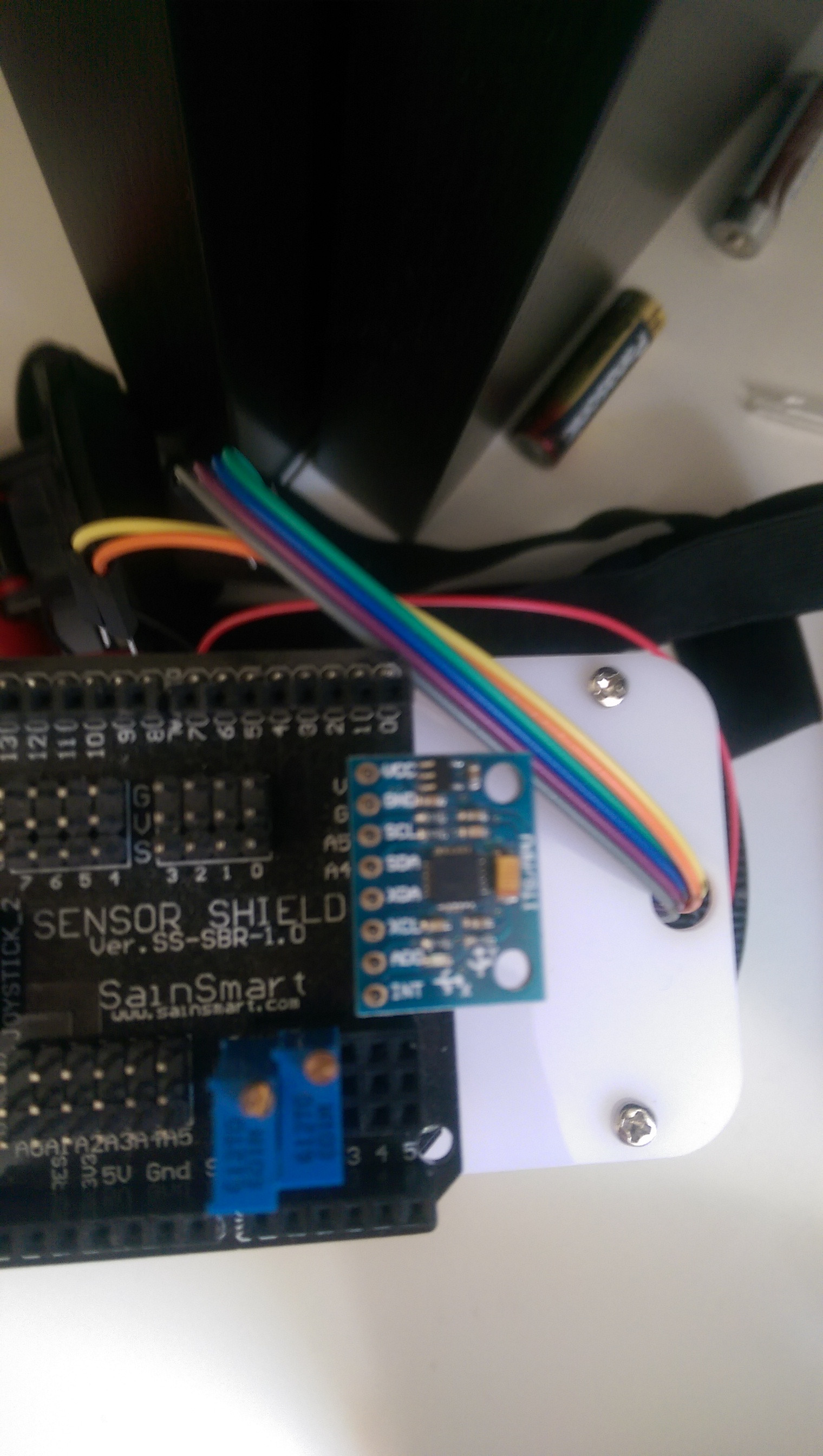
enter image description here

1
  • Please post your code and, if not included in the above links, the schematic. Commented Jun 8, 2015 at 12:47

1 Answer 1

0

The shield you linked to is no longer sold.

The current version is enter image description here

But it has no special connection for an MPU6050 breakout (and BTW that same 6050 board is $6 about everywhere else). A shield serves no purpose for just the 6050 really.

If you connected the 6050 to the I2C lines (aka A4 & A5), Then you also need to connect an additional interrupt line. If you are using unmodified example code, it depends on the interrupt being connected.

Here is a post made a while back using the 6050

http://www.spiked3.com/very-cool-imu-demo/

It is possible to use the 6050 without interrupts but you would have to (understand and) modify the standard example code.

Update: I knew you had a different board, and it had a connector for the 6050, the comment was that the link you provided, since it was 'no longer available', did not link to any documentation. Without a schematic it can not be known how it is hooked up beyond simple I2C. As you are using other devices I am not familiar with, I would expect some sort of conflict on the i2C bus maybe. Are all i2c bus devices using the same reference voltage? It does not matter if they are all 5v or all 3.3V as long as they are all the same.

Since you say 'nothing is printed' and your second line of setup is 'initialize' gyro, odds are good it is not getting past that. Simple (archaic) debugging, put a print (and a small delay) before and after the call to initialize.

My code uses the following for Wire.begin

#if I2CDEV_IMPLEMENTATION == I2CDEV_ARDUINO_WIRE
    Wire.begin();
    TWBR = 24; // 400kHz I2C clock (200kHz if CPU is 8MHz)
#elif I2CDEV_IMPLEMENTATION == I2CDEV_BUILTIN_FASTWIRE
    Fastwire::setup(400, true);
#endif

I dont know if your Arduino is different and if it would make any difference.

I have a line after initialize

mpu.testConnection();

That may or may not help you.

FYI PI is already defined, as is DEG_TO_RAD and RAD_TO_DEG

if (abs(RAD_TO_DEG * headingDelta) > .1F)
    poseChanged = true;

Update: I just looked quickly at the code, and the only thing initialize does is write to i2c, it never waits really. And that means writing to I2C is hanging. I ran into this once when I had an unpowered device on the bus. I thought it would not harm, but I was wrong. Does the power light on the mpu come on? (is it really getting power?) I have run them at 3.3v and 5V so I do not think that would be a problem, but if you can, switch it to 3.3V to be sure. Getting down to the nitty gritty, you could check if the default pullup resistors are still on the board and did not get accidentally knocked off. Even better would be to try it with a known good MPU. I have about 10 of them within reach :P (spiked3.com)

6
  • I do not fully get you, on the shield I have on one of the sides there are eight holes where a mpu6050 goes, as it says mupu6050 beside them. I have added my code along with a picture of the sensor on my shield Commented Jun 9, 2015 at 11:56
  • Yes it is not getting past the accelgyro.initialize(); Commented Jun 9, 2015 at 14:34
  • Sorry to say but at this point I learned how to (buy and) use a saleae logic analyzer. Start a new sketch with nothing but the MPU code. If that works, then its a conflict with the 24l01 maybe?
    – user6569
    Commented Jun 9, 2015 at 14:48
  • I tried a mpu6050 example and that did not work either Commented Jun 9, 2015 at 15:12
  • The light does not come always as the mpu6050 is not stuck to the pins, however when I press the mup6050 against the pins to make the light light up the arduino gives me this error "programmer is not responding avrdude: stk500_getsync() attempt 1 of 1: not in sync: resp=0x00" Commented Jun 9, 2015 at 17:56

Your Answer

By clicking “Post Your Answer”, you agree to our terms of service and acknowledge you have read our privacy policy.

Not the answer you're looking for? Browse other questions tagged or ask your own question.