corrected spelling of "USB"; changed "v" to "V" when used as an abbreviation for volt(s)
Source Link

I am a novice user of Arduino. I am not sure whether I can connect both USB and external supply through power adaptor to Arduino simultaneously. Would this burn the controller?

Lets study the schematic of Arduino UNO R3

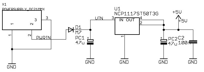
The input from the power supply plug (PWRIN, the power jack) goes through a diode D1 (to prevent reverse polarity), and feeds a NCP1117 regulator that down converts it to the 5v supply that feeds the 5v parts.
Power input

The alternative supply comes from the USB plug (USBVCC). The relevant circuit is shown below
enter image description here

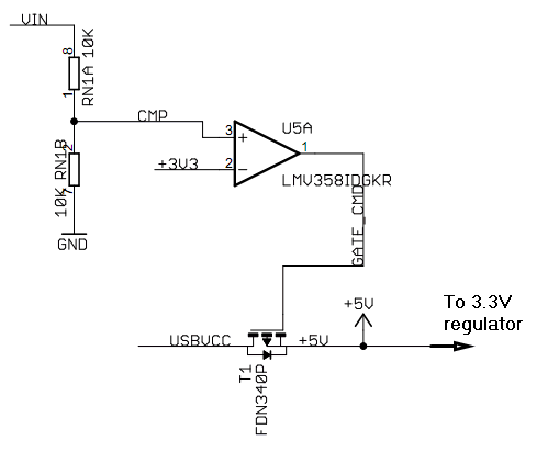
The USB power lines goes through a P-mosfet (T1) that operates as a switch and then goes to the +5V node (that is the +5v regulator output as shown in the first schematic).

The mosfet is controlled by an LMV358 operational amplifier (OPAMP) that operates as a comparator.
The negative input of the opamp is tied to 3.3v3V and the positive one fed through a voltage divider with half the Vin supply level.

  • When Vin >6.6V then the + input of the opamp become higher than the - input and the opamp turns the mosfet off.

  • When Vin <6.6V then the + input of the opamp become lower than the - input and the opamp turns the mosfet on.

Note that Vin is after the input diode so it's about 0.6v6V lower than the external connected power supply level. So when there is power supply connected to the power input that is higher than 6.6v+06V+0.6v6V (where 0.6v6V is the diode D1 voltage drop), then the USB supply line is cutoff (because the mosfet turns off) and the power is provided from the power plug. Connecting or disconnecting the USPUSB supply in this case will not make a difference, so you can have both power supplies connected simultaneously, only when the power input drops below the specified level (about 6.6V+0.6V=7.2V), the USB will start powering the board.

I am a novice user of Arduino. I am not sure whether I can connect both USB and external supply through power adaptor to Arduino simultaneously. Would this burn the controller?

Lets study the schematic of Arduino UNO R3

The input from the power supply plug (PWRIN, the power jack) goes through a diode D1 (to prevent reverse polarity), and feeds a NCP1117 regulator that down converts it to the 5v supply that feeds the 5v parts.

Power input

The alternative supply comes from the USB plug (USBVCC). The relevant circuit is shown below

enter image description here

The USB power lines goes through a P-mosfet (T1) that operates as a switch and then goes to the +5V node (that is the +5v regulator output as shown in the first schematic).

The mosfet is controlled by an LMV358 operational amplifier (OPAMP) that operates as a comparator.
The negative input of the opamp is tied to 3.3v and the positive one fed through a voltage divider with half the Vin supply level.

  • When Vin >6.6V then the + input of the opamp become higher than the - input and the opamp turns the mosfet off.

  • When Vin <6.6V then the + input of the opamp become lower than the - input and the opamp turns the mosfet on.

Note that Vin is after the input diode so it's about 0.6v lower than the external connected power supply level. So when there is power supply connected to the power input that is higher than 6.6v+0.6v (where 0.6v is the diode D1 voltage drop), then the USB supply line is cutoff (because the mosfet turns off) and the power is provided from the power plug. Connecting or disconnecting the USP supply in this case will not make a difference, so you can have both power supplies connected simultaneously, only when the power input drops below the specified level (about 6.6V+0.6V=7.2V), the USB will start powering the board.

I am a novice user of Arduino. I am not sure whether I can connect both USB and external supply through power adaptor to Arduino simultaneously. Would this burn the controller?

Lets study the schematic of Arduino UNO R3

The input from the power supply plug (PWRIN, the power jack) goes through a diode D1 (to prevent reverse polarity), and feeds a NCP1117 regulator that down converts it to the 5v supply that feeds the 5v parts.

Power input

The alternative supply comes from the USB plug (USBVCC). The relevant circuit is shown below

enter image description here

The USB power lines goes through a P-mosfet (T1) that operates as a switch and then goes to the +5V node (that is the +5v regulator output as shown in the first schematic).

The mosfet is controlled by an LMV358 operational amplifier (OPAMP) that operates as a comparator.
The negative input of the opamp is tied to 3.3V and the positive one fed through a voltage divider with half the Vin supply level.

  • When Vin >6.6V then the + input of the opamp become higher than the - input and the opamp turns the mosfet off.

  • When Vin <6.6V then the + input of the opamp become lower than the - input and the opamp turns the mosfet on.

Note that Vin is after the input diode so it's about 0.6V lower than the external connected power supply level. So when there is power supply connected to the power input that is higher than 6.6V+0.6V (where 0.6V is the diode D1 voltage drop), then the USB supply line is cutoff (because the mosfet turns off) and the power is provided from the power plug. Connecting or disconnecting the USB supply in this case will not make a difference, so you can have both power supplies connected simultaneously, only when the power input drops below the specified level (about 6.6V+0.6V=7.2V), the USB will start powering the board.

Source Link
alexan_e
  • 1.8k
  • 1
  • 13
  • 16

I am a novice user of Arduino. I am not sure whether I can connect both USB and external supply through power adaptor to Arduino simultaneously. Would this burn the controller?

Lets study the schematic of Arduino UNO R3

The input from the power supply plug (PWRIN, the power jack) goes through a diode D1 (to prevent reverse polarity), and feeds a NCP1117 regulator that down converts it to the 5v supply that feeds the 5v parts.

Power input

The alternative supply comes from the USB plug (USBVCC). The relevant circuit is shown below

enter image description here

The USB power lines goes through a P-mosfet (T1) that operates as a switch and then goes to the +5V node (that is the +5v regulator output as shown in the first schematic).

The mosfet is controlled by an LMV358 operational amplifier (OPAMP) that operates as a comparator.
The negative input of the opamp is tied to 3.3v and the positive one fed through a voltage divider with half the Vin supply level.

  • When Vin >6.6V then the + input of the opamp become higher than the - input and the opamp turns the mosfet off.

  • When Vin <6.6V then the + input of the opamp become lower than the - input and the opamp turns the mosfet on.

Note that Vin is after the input diode so it's about 0.6v lower than the external connected power supply level. So when there is power supply connected to the power input that is higher than 6.6v+0.6v (where 0.6v is the diode D1 voltage drop), then the USB supply line is cutoff (because the mosfet turns off) and the power is provided from the power plug. Connecting or disconnecting the USP supply in this case will not make a difference, so you can have both power supplies connected simultaneously, only when the power input drops below the specified level (about 6.6V+0.6V=7.2V), the USB will start powering the board.