Fixed typos in code and description and improved fomatting
Source Link

parallel communication is possible using arduino you need to use the portsports for example port A and then a rx tx pins.

code setting up ports

transmit  function

#include <Wire.h>
#include <Arduino.h>

byte i = 0;
int intpin = 44;
int rcv_ready = 45;

void setup() {
  DDRA = B11111111; // Output
  DDRC = B11111111; // Output
  pinMode(intpin, OUTPUT);
  pinMode(rcv_ready, INPUT);
}

void loop() {
  transmit();
}

void transmit() {
  PORTA = i++
  PORTC = i;
  digitalWrite(intpin, HIGH);
  while (rcv_ready == LOW) {}
  digitalWrite(intpin, LOW);
  
  delay(299);
}

Here we set up the two ports DDRA and DDRC to be output ports by using the mask B11111111; We set the interrupt pin to port 44 and set it is an output and we set the receive pin to be 45 and an input. Then we call transmit in the loop. Where we then set port A andand port C to equal i++ and Ii respectively  . And then toggle the signal to say we have transmitted a new message. This will get picked up by the Slave-input.

Slave input slave input  code blink  function for interrupt

#include <Arduino.h>

byte x = 0;
byte y = 0;
int rcv_ready = 45;

void setup() {
  DDRA = B00000000; // Input
  DDRC = B00000000; // Input
  Serial.begin(19200);
  attachInterrupt(5, blink, RISING);
  pinMode(rcv_ready, OUTPUT);
  digitalWrite(rcv_ready, LOW);
}

void loop() {}

void blink() {
  x = PINA;
  y = PINC;
  delay(100);
  digitalWrite(rcv_ready, HIGH);
  delay(100);
  digitalWrite(rcv_ready, LOW);
  Serial.print(x);
  Serial.print(" , ");
  Serial.println(y);
}

Here we setset up the two ports DDRA and DDRC to be input ports by using the mask B00000000; We then set the baud ratebaud rate as 19200 which matches the saterate set by the master

Here we set the interrupt to be 5 which is pin 18 and tell it to call blink on an interrupt. We then read the values from PORTA and PORTC and then we output it to the serial monitor screen. We also send backback the acknowledgementacknowledgement of receipt to the master using pinpin 45

parallel communication is possible using arduino you need to use the ports for example port A and then a rx tx pins.

code setting up ports

transmit  function

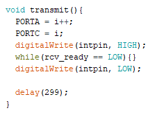
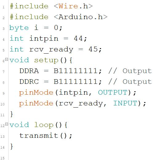
Here we set up the two ports DDRA and DDRC to be output ports by using the mask B11111111; We set the interrupt pin to port 44 and set it is an output and we set the receive pin to be 45 and an input. Then we call transmit in the loop. Where we then set port A and port C to equal i++ and I respectively  . And then toggle the signal to say we have transmitted a new message. This will get picked up by the Slave-input.

Slave input slave input  code blink  function for interrupt

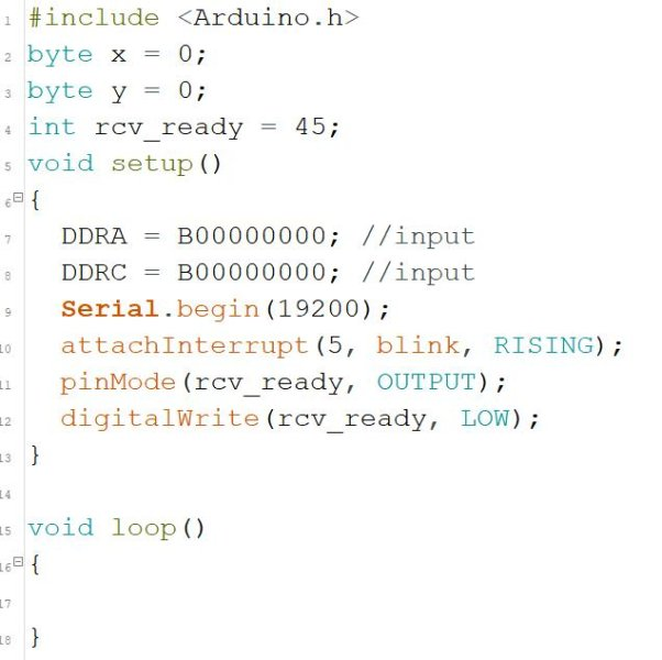
Here we set up the two ports DDRA and DDRC to be input ports by using the mask B00000000; We then set the baud rate as 19200 which matches the sate set by the master

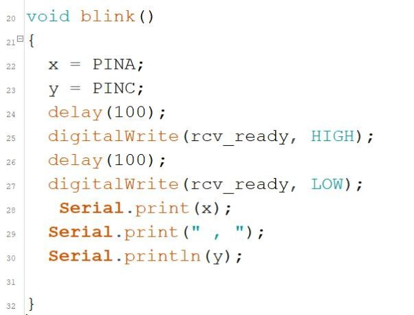
Here we set the interrupt to be 5 which is pin 18 and tell it to call blink on an interrupt. We then read the values from PORTA and PORTC and then we output it to the serial monitor screen. We also send back the acknowledgement of receipt to the master using pin 45

parallel communication is possible using arduino you need to use the ports for example port A and then a rx tx pins.

#include <Wire.h>
#include <Arduino.h>

byte i = 0;
int intpin = 44;
int rcv_ready = 45;

void setup() {
  DDRA = B11111111; // Output
  DDRC = B11111111; // Output
  pinMode(intpin, OUTPUT);
  pinMode(rcv_ready, INPUT);
}

void loop() {
  transmit();
}

void transmit() {
  PORTA = i++
  PORTC = i;
  digitalWrite(intpin, HIGH);
  while (rcv_ready == LOW) {}
  digitalWrite(intpin, LOW);
  
  delay(299);
}

Here we set up the two ports DDRA and DDRC to be output ports by using the mask B11111111; We set the interrupt pin to port 44 and set it is an output and we set the receive pin to be 45 and an input. Then we call transmit in the loop. Where we then set port A and port C to equal i++ and i respectively. And then toggle the signal to say we have transmitted a new message. This will get picked up by the Slave-input.

Slave input

#include <Arduino.h>

byte x = 0;
byte y = 0;
int rcv_ready = 45;

void setup() {
  DDRA = B00000000; // Input
  DDRC = B00000000; // Input
  Serial.begin(19200);
  attachInterrupt(5, blink, RISING);
  pinMode(rcv_ready, OUTPUT);
  digitalWrite(rcv_ready, LOW);
}

void loop() {}

void blink() {
  x = PINA;
  y = PINC;
  delay(100);
  digitalWrite(rcv_ready, HIGH);
  delay(100);
  digitalWrite(rcv_ready, LOW);
  Serial.print(x);
  Serial.print(" , ");
  Serial.println(y);
}

Here we set up the two ports DDRA and DDRC to be input ports by using the mask B00000000; We then set the baud rate as 19200 which matches the rate set by the master

Here we set the interrupt to be 5 which is pin 18 and tell it to call blink on an interrupt. We then read the values from PORTA and PORTC and then we output it to the serial monitor screen. We also send back the acknowledgement of receipt to the master using pin 45

Source Link

parallel communication is possible using arduino you need to use the ports for example port A and then a rx tx pins.

code setting up ports

transmit  function

Here we set up the two ports DDRA and DDRC to be output ports by using the mask B11111111; We set the interrupt pin to port 44 and set it is an output and we set the receive pin to be 45 and an input. Then we call transmit in the loop. Where we then set port A and port C to equal i++ and I respectively . And then toggle the signal to say we have transmitted a new message. This will get picked up by the Slave-input.

Slave input slave input  code blink  function for interrupt

Here we set up the two ports DDRA and DDRC to be input ports by using the mask B00000000; We then set the baud rate as 19200 which matches the sate set by the master

Here we set the interrupt to be 5 which is pin 18 and tell it to call blink on an interrupt. We then read the values from PORTA and PORTC and then we output it to the serial monitor screen. We also send back the acknowledgement of receipt to the master using pin 45