added 286 characters in body
Source Link
Rudy
  • 993
  • 5
  • 11

I would like to know why when one device is bad (or not powered) on I2C, it screws up the other devices.

The I2C lines need to have a pull up resistor to provide the high. The master device, and the slave devices, ground the line to provide a low, but they release the line, and not drive it at all, in order to provide the high.

enter image description here

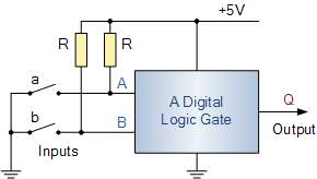
Consider switches a and b to be inside the I2C device. When the switch a is open point A will be at 5 volts. When switch a is closed, point A will be at 0 volts.

Now if you had a second set of R resistors on the same line, but powered from their own 5 volt power supply, the same voltages will be seen at A when switch a is open (5 volts) and switch a is closed (0 volts).

But now if we kill the supply feeding the second set of R resistors (sorry that I can't show them in a picture) instead of pulling up to 5 volts (because we killed the 5 volts) the resistors will be pulling down due to whatever other loads there are on the killed 5 volt supply. And just for argument sake, let's say the killed 5 volt supply was at 0 volts.

So if one set of resistors is pulling up to 5 volts (the still powered pair) and one pulling down (the killed pair) then the voltage at points A and B will not be as high as the 5 volts we would see when the switches are open. If all the resistors R were the same value, and the killed supply was at 0 volts, then the highest voltage at A or B would be 2.5 volts. And that is not a good high.

So the additional device, that is not being powered, has disrupted the communitations, preventing true highs. Lows are not affected as the switch will pull the line low.

I don't know the values of all your pull up resistors, and don't know how low the dead supply goes, so I can't say what the new lower highest voltage is. But it seems that it is low enough to make the communications stop working.

And the resistor are not the only thing that can be disgusting the high. The unpowered chip can be providing unexpected current paths. Most port pins have an internal diode to Vcc. And since the chip has no power on Vcc the current on the I2C lines can follow that path to ground.

Also, I think you have drawn the resistors wrong. If they were in series with the SDA and the SCL pins there would be no communications because the 1k resistors doesn't allow the SDA line to be pulled low enough. I think those resistors are pull up resistors. Maybe you can take another look and confirm the connection.

I would like to know why when one device is bad (or not powered) on I2C, it screws up the other devices.

The I2C lines need to have a pull up resistor to provide the high. The master device, and the slave devices, ground the line to provide a low, but they release the line, and not drive it at all, in order to provide the high.

enter image description here

Consider switches a and b to be inside the I2C device. When the switch a is open point A will be at 5 volts. When switch a is closed, point A will be at 0 volts.

Now if you had a second set of R resistors on the same line, but powered from their own 5 volt power supply, the same voltages will be seen at A when switch a is open (5 volts) and switch a is closed (0 volts).

But now if we kill the supply feeding the second set of R resistors (sorry that I can't show them in a picture) instead of pulling up to 5 volts (because we killed the 5 volts) the resistors will be pulling down due to whatever other loads there are on the killed 5 volt supply. And just for argument sake, let's say the killed 5 volt supply was at 0 volts.

So if one set of resistors is pulling up to 5 volts (the still powered pair) and one pulling down (the killed pair) then the voltage at points A and B will not be as high as the 5 volts we would see when the switches are open. If all the resistors R were the same value, and the killed supply was at 0 volts, then the highest voltage at A or B would be 2.5 volts. And that is not a good high.

So the additional device, that is not being powered, has disrupted the communitations, preventing true highs. Lows are not affected as the switch will pull the line low.

I don't know the values of all your pull up resistors, and don't know how low the dead supply goes, so I can't say what the new lower highest voltage is. But it seems that it is low enough to make the communications stop working.

And the resistor are not the only thing that can be disgusting the high. The unpowered chip can be providing unexpected current paths. Most port pins have an internal diode to Vcc. And since the chip has no power on Vcc the current on the I2C lines can follow that path to ground.

Also, I think you have drawn the resistors wrong. If they were in series with the SDA and the SCL pins there would be no communications because the 1k resistors doesn't allow the SDA line to be pulled low enough. I think those resistors are pull up resistors. Maybe you can take another look and confirm the connection.

Source Link
Rudy
  • 993
  • 5
  • 11

I would like to know why when one device is bad (or not powered) on I2C, it screws up the other devices.

The I2C lines need to have a pull up resistor to provide the high. The master device, and the slave devices, ground the line to provide a low, but they release the line, and not drive it at all, in order to provide the high.

enter image description here

Consider switches a and b to be inside the I2C device. When the switch a is open point A will be at 5 volts. When switch a is closed, point A will be at 0 volts.

Now if you had a second set of R resistors on the same line, but powered from their own 5 volt power supply, the same voltages will be seen at A when switch a is open (5 volts) and switch a is closed (0 volts).

But now if we kill the supply feeding the second set of R resistors (sorry that I can't show them in a picture) instead of pulling up to 5 volts (because we killed the 5 volts) the resistors will be pulling down due to whatever other loads there are on the killed 5 volt supply. And just for argument sake, let's say the killed 5 volt supply was at 0 volts.

So if one set of resistors is pulling up to 5 volts (the still powered pair) and one pulling down (the killed pair) then the voltage at points A and B will not be as high as the 5 volts we would see when the switches are open. If all the resistors R were the same value, and the killed supply was at 0 volts, then the highest voltage at A or B would be 2.5 volts. And that is not a good high.

So the additional device, that is not being powered, has disrupted the communitations, preventing true highs. Lows are not affected as the switch will pull the line low.

I don't know the values of all your pull up resistors, and don't know how low the dead supply goes, so I can't say what the new lower highest voltage is. But it seems that it is low enough to make the communications stop working.

Also, I think you have drawn the resistors wrong. If they were in series with the SDA and the SCL pins there would be no communications because the 1k resistors doesn't allow the SDA line to be pulled low enough. I think those resistors are pull up resistors. Maybe you can take another look and confirm the connection.