Tweeted twitter.com/StackArduino/status/802422354739609600
improved grammar and formatting and added tag
Source Link
jfpoilpret
  • 9.1k
  • 7
  • 37
  • 54

I am working on a project for knowing the position the of a DC motor which has a hall sensor built into it. I am a newbie into programming using the Arduino Uno R3. After some forum search and self checks, iI cannot pass this hurdle. I hope I can frame the questions properly here.

My Problem: The DC motor hall sensor sends out 2 high pulse of 11.3V - 13V with a duration of 2.8ms for each revolution. My Arduino interrupt pin doesn't read the high pulse as it gives me "0" count after motor spin (I run 50 loops and results remain the same).

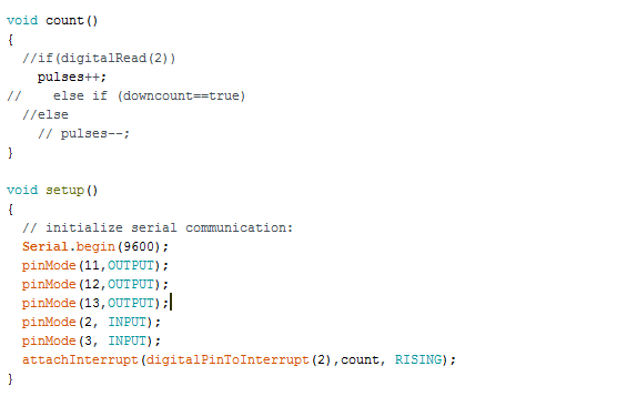
Interupt pin asssigment with function call

On my breadboard, iI use a voltage divider to reduce hall-effect ouput from max 13V to 5V so that the Arduino pin 2 can read rising voltage when it jumps to 5V (low should be 2.5V).

Couple of things I noted during the motor spin -

a) The millis() function returns 79-81ms per sketch run

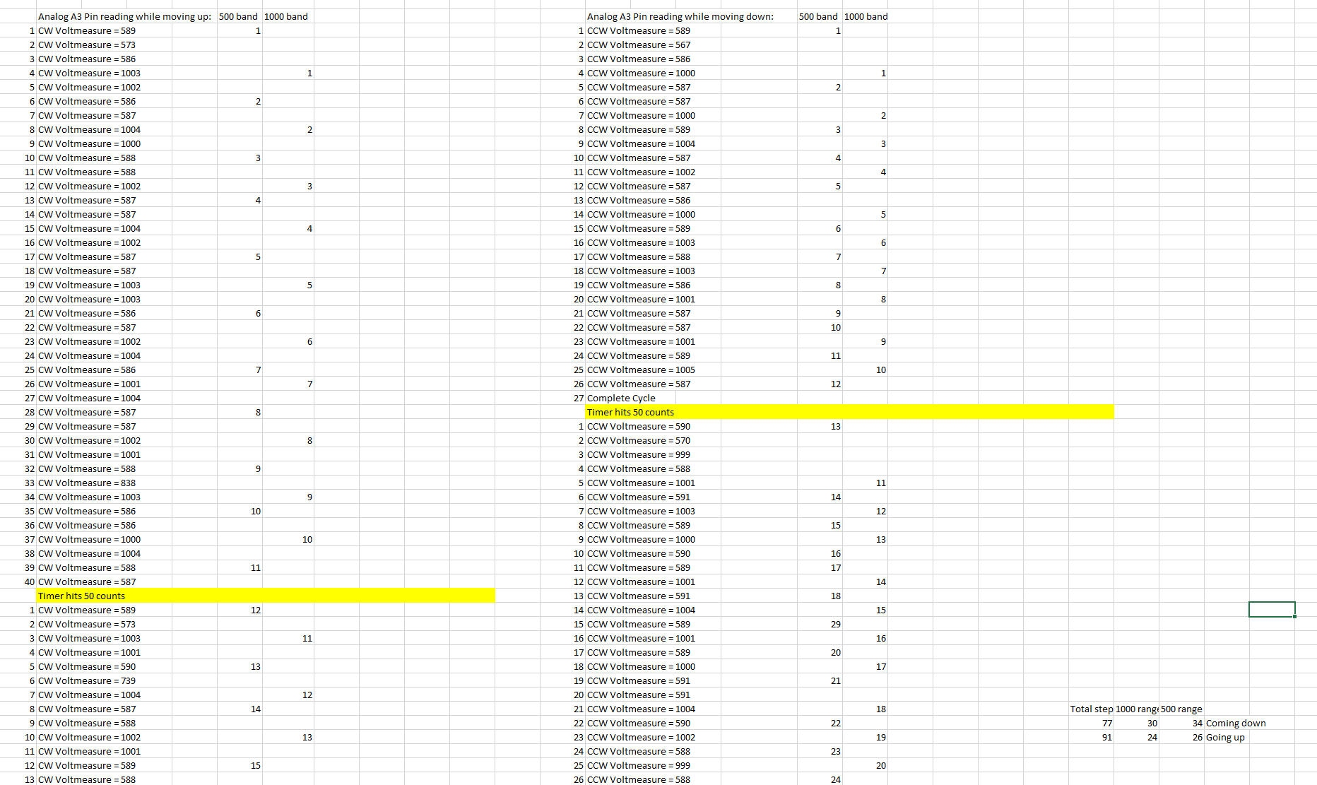
b) The same hall sensor output if connected to analog pin reads 580,590,590,1001, 1012, 580, 580.. etc. I cannot guagegauge position of the motor by using these values as they are inconsistent on the way up v/sVs. way down.

I have attached analog readings while going up and down in snap shot below: enter image description here 2 questionquestions I have:
  1. Why is the pin 2 not detecting a high pulse? will it not be able to read 2.8ms durations because of motor speed (9.5 rev/s or 570rpm)?
  2. Is it possible to gauge anything from Analog read function? Am iI missing something?

Thanks in advance for all responses.. Any questions regarding the circuit, I will be more than happy to post them.

I am working on a project for knowing the position the of DC motor which has a hall sensor built into it. I am newbie into programming using the Arduino Uno R3. After some forum search and self checks, i cannot pass this hurdle. I hope I can frame the questions properly here.

My Problem: The DC motor hall sensor sends out 2 high pulse of 11.3V - 13V with a duration of 2.8ms for each revolution. My Arduino interrupt pin doesn't read the high pulse as it gives me "0" count after motor spin (I run 50 loops and results remain the same).

Interupt pin asssigment with function call

On my breadboard, i use a voltage divider to reduce hall-effect ouput from max 13V to 5V so that the Arduino pin 2 can read rising voltage when it jumps to 5V (low should be 2.5V).

Couple of things I noted during the motor spin -

a) The millis() function returns 79-81ms per sketch run

b) The same hall sensor output if connected to analog pin reads 580,590,590,1001, 1012, 580, 580.. etc. I cannot guage position of the motor by using these values as they are inconsistent on the way up v/s way down.

I have attached analog readings while going up and down in snap shot below: enter image description here 2 question I have:

  1. Why is the pin 2 not detecting a high pulse? will it not be able to read 2.8ms durations because of motor speed (9.5 rev/s or 570rpm)?
  2. Is it possible to gauge anything from Analog read function? Am i missing something?

Thanks in advance for all responses.. Any questions regarding the circuit, I will be more than happy to post them.

I am working on a project for knowing the position of a DC motor which has a hall sensor built into it. I am a newbie into programming using the Arduino Uno R3. After some forum search and self checks, I cannot pass this hurdle. I hope I can frame the questions properly here.

My Problem: The DC motor hall sensor sends out 2 high pulse of 11.3V - 13V with a duration of 2.8ms for each revolution. My Arduino interrupt pin doesn't read the high pulse as it gives me "0" count after motor spin (I run 50 loops and results remain the same).

Interupt pin asssigment with function call

On my breadboard, I use a voltage divider to reduce hall-effect ouput from max 13V to 5V so that the Arduino pin 2 can read rising voltage when it jumps to 5V (low should be 2.5V).

Couple of things I noted during the motor spin -

a) The millis() function returns 79-81ms per sketch run

b) The same hall sensor output if connected to analog pin reads 580,590,590,1001, 1012, 580, 580.. etc. I cannot gauge position of the motor by using these values as they are inconsistent on the way up Vs. way down.

I have attached analog readings while going up and down in snap shot below: enter image description here 2 questions I have:

  1. Why is the pin 2 not detecting a high pulse? will it not be able to read 2.8ms durations because of motor speed (9.5 rev/s or 570rpm)?
  2. Is it possible to gauge anything from Analog read function? Am I missing something?

Thanks in advance for all responses.. Any questions regarding the circuit, I will be more than happy to post them.

improved grammar and formatting and added tag
Source Link

Detecting a 2.8ms pulse using a arduino UNOArduino Uno

I am working on a project for knowing the position the of DC motor which has a hall sensor built into it. I am newbie into programming using the arduino unoArduino Uno R3. After some forum search and self checks, i cannot pass this hurdle. I hope iI can frame the questions properly here.

My Problem: The DC motor hall sensor sends out 2 high pulse of 11.3V - 13V with a duration of 2.8ms for each revolution. My arduinoArduino interrupt pin doesn't read the high pulse as it gives me "0" count after motor spin (I run 50 loops and results remain the same).

Interupt pin asssigment with function call

On my breadboard, i use a voltage divider to reduce hall-effect ouput from max 13V to 5V so that the arduinoArduino pin 2 can read rising voltage when it jumps to 5V (low should be 2.5V).

Couple of things iI noted during the motor spin -

a) The millis()millis() function returns 79-81ms per sketch run

b) The same hall sensor output if connected to analog pin reads 580,590,590,1001, 1012, 580, 580.. etc. I cannot guage position of the motor by using these values as they are inconsistent on the way up v/s way down.

I have attached analog readings while going up and down in snap shot below: enter image description here 2 question iI have:

  1. Why is the pin 2 not detecting a high pulse? will it not be able to read 2.8ms durations because of motor speed (9.5 rev/s or 570rpm)?
  2. Is it possible to gauge anything from Analog read function? Am i missing something?

Thanks in advance for all responses.. Any questions regarding the circuit, iI will be more than happy to post them.

Detecting a 2.8ms pulse using a arduino UNO

I am working on a project for knowing the position the of DC motor which has a hall sensor built into it. I am newbie into programming using the arduino uno R3. After some forum search and self checks, i cannot pass this hurdle. I hope i can frame the questions properly here.

My Problem: The DC motor hall sensor sends out 2 high pulse of 11.3V - 13V with a duration of 2.8ms for each revolution. My arduino interrupt pin doesn't read the high pulse as it gives me "0" count after motor spin (I run 50 loops and results remain the same).

Interupt pin asssigment with function call

On my breadboard, i use a voltage divider to reduce hall-effect ouput from max 13V to 5V so that the arduino pin 2 can read rising voltage when it jumps to 5V (low should be 2.5V).

Couple of things i noted during the motor spin -

a) The millis() function returns 79-81ms per sketch run

b) The same hall sensor output if connected to analog pin reads 580,590,590,1001, 1012, 580, 580.. etc. I cannot guage position of the motor by using these values as they are inconsistent on the way up v/s way down.

I have attached analog readings while going up and down in snap shot below: enter image description here 2 question i have:

  1. Why is the pin 2 not detecting a high pulse? will it not be able to read 2.8ms durations because of motor speed (9.5 rev/s or 570rpm)?
  2. Is it possible to gauge anything from Analog read function? Am i missing something?

Thanks in advance for all responses.. Any questions regarding the circuit, i will be more than happy to post them.

Detecting a 2.8ms pulse using a Arduino Uno

I am working on a project for knowing the position the of DC motor which has a hall sensor built into it. I am newbie into programming using the Arduino Uno R3. After some forum search and self checks, i cannot pass this hurdle. I hope I can frame the questions properly here.

My Problem: The DC motor hall sensor sends out 2 high pulse of 11.3V - 13V with a duration of 2.8ms for each revolution. My Arduino interrupt pin doesn't read the high pulse as it gives me "0" count after motor spin (I run 50 loops and results remain the same).

Interupt pin asssigment with function call

On my breadboard, i use a voltage divider to reduce hall-effect ouput from max 13V to 5V so that the Arduino pin 2 can read rising voltage when it jumps to 5V (low should be 2.5V).

Couple of things I noted during the motor spin -

a) The millis() function returns 79-81ms per sketch run

b) The same hall sensor output if connected to analog pin reads 580,590,590,1001, 1012, 580, 580.. etc. I cannot guage position of the motor by using these values as they are inconsistent on the way up v/s way down.

I have attached analog readings while going up and down in snap shot below: enter image description here 2 question I have:

  1. Why is the pin 2 not detecting a high pulse? will it not be able to read 2.8ms durations because of motor speed (9.5 rev/s or 570rpm)?
  2. Is it possible to gauge anything from Analog read function? Am i missing something?

Thanks in advance for all responses.. Any questions regarding the circuit, I will be more than happy to post them.

Post Migrated Here from electronics.stackexchange.com (revisions)
Source Link

Detecting a 2.8ms pulse using a arduino UNO

I am working on a project for knowing the position the of DC motor which has a hall sensor built into it. I am newbie into programming using the arduino uno R3. After some forum search and self checks, i cannot pass this hurdle. I hope i can frame the questions properly here.

My Problem: The DC motor hall sensor sends out 2 high pulse of 11.3V - 13V with a duration of 2.8ms for each revolution. My arduino interrupt pin doesn't read the high pulse as it gives me "0" count after motor spin (I run 50 loops and results remain the same).

Interupt pin asssigment with function call

On my breadboard, i use a voltage divider to reduce hall-effect ouput from max 13V to 5V so that the arduino pin 2 can read rising voltage when it jumps to 5V (low should be 2.5V).

Couple of things i noted during the motor spin -

a) The millis() function returns 79-81ms per sketch run

b) The same hall sensor output if connected to analog pin reads 580,590,590,1001, 1012, 580, 580.. etc. I cannot guage position of the motor by using these values as they are inconsistent on the way up v/s way down.

I have attached analog readings while going up and down in snap shot below: enter image description here 2 question i have:

  1. Why is the pin 2 not detecting a high pulse? will it not be able to read 2.8ms durations because of motor speed (9.5 rev/s or 570rpm)?
  2. Is it possible to gauge anything from Analog read function? Am i missing something?

Thanks in advance for all responses.. Any questions regarding the circuit, i will be more than happy to post them.